
Doorbell
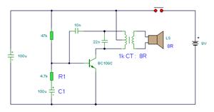
The project incorporates a silicon chip (M66T-02B) that plays a pre-defined melody, specifically designed for use as a doorbell. The circuit design employs a timer mechanism to ensure that the melody plays fully when the doorbell is pressed. The use of a 1000 µF electrolytic capacitor serves as a crucial component, allowing the relay to remain engaged long enough to complete the tune. This capacitor is charged when the doorbell push switch is activated, and it discharges slowly, keeping the relay activated for a brief period.
The relay (RLA1) is a key component in this circuit as it allows for the control of higher current loads, such as the loudspeaker, while being driven by a low-current signal. The separation of power supplies for the relay and the loudspeaker is essential to ensure that each component operates within its specified voltage and current ratings. The relay's operation is controlled by a transistor (TR1), which acts as a switch. The diode (D1) is included in the circuit to prevent back EMF generated by the relay coil from damaging the transistor when the relay is switched off.
The overall circuit design emphasizes the importance of component selection and layout, ensuring that the melody is played correctly and the doorbell functions reliably. The use of a schematic diagram aids in visualizing the connections and functionality of each part of the circuit, providing a clear reference for assembly and troubleshooting.I designed this project for another boy who had a much bigger box of electronic scrap than me so he supplied most of the bits for it. I made it in few evenings besides doing my homework. We wanted it to play a bit of a tune so we looked through the Maplin Catalogue and on page 1200 there is a silicon chip type M66T which will do just this.
The chi p is available in several versions, playing different tunes and we settled on the M66T-02B playing twinkle twinkle little star. The cost of the chip was £0. 49 and needs no added output stage to drive a small loudspeaker. There was a typical sample circuit in the catalogue so I built it to this circuit and I found that the volume was high enough but the silicon chip played continuously as long as the supply was maintained.
The problem was how was I going to get that to be a doorbell A lazy way of doing it would be to put the bell push in series with the battery supply but since most people press a bell push in the same way that they press the keys on a computer keyboard, this would only give one or two notes of the melody so I decided that a timer circuit was needed which would trigger when the push switch was operated and would hold the circuit on for the few seconds of the tune. I looked through the junk box again where I got the loudspeaker from and found a 1000 µf electrolytic capacitor which would hold its charge for a few seconds and keep the relay RLA1 operated for the time of the tune.
The relay needed 9 volts at low current but the loudspeaker circuit needed only 3 volts at a higher current so I decided to have separate batteries to operate the different parts of the circuit. Also if the transistor switches the current to the IC directly it gives an odd effect at the end of the tune as if the musician playing it had been shot and was still trying to play it as he collapsed.
My uncle drew out the schematic for me because my own attempt was a bit too messy to reproduce. The full circuit is shown below. The diode D1 is to protect TR1 from the high voltages produced when the current in the relay coil is switched off and the coil magnetic field collapses. 🔗 External reference
Related Circuits
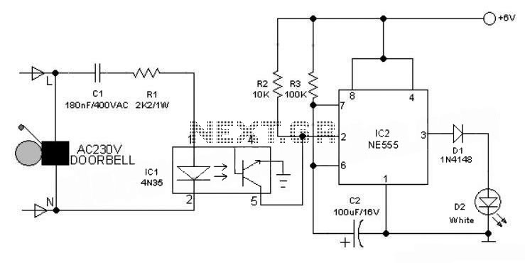
This 6V battery-operated doorbell light circuit can be connected in parallel with any existing AC 230V doorbell. When the doorbell switch is pressed, the bell sounds as usual, and the AC mains supply available across the doorbell is routed...

This is a circuit design for a doorbell that produces a sound resembling that of a bird. The circuit is controlled by an NPN transistor. The operation begins when P1 is set to an experimental value, starting with approximately...
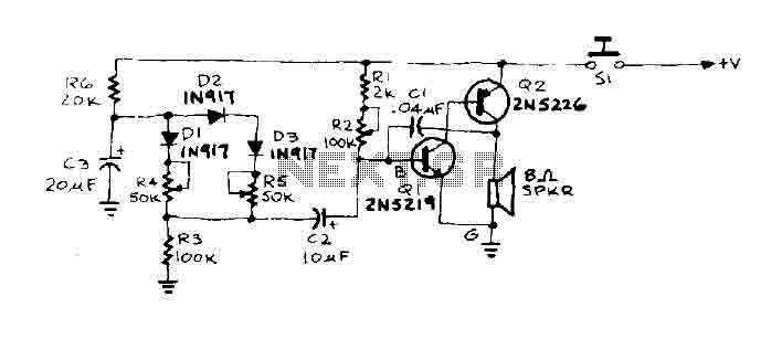
When the door is pushed, a whisper is heard that transitions to a higher frequency. The oscillator frequency is determined by the audio frequency coupling capacitance, C1, and the resistance connected between the base of transistor Q1 and ground....
In all the houses exist the bells in the door. All want, they have the possibility of being possible to change the intensity, the tone of sound. With this circuit we have this possibility. With the materials round the...
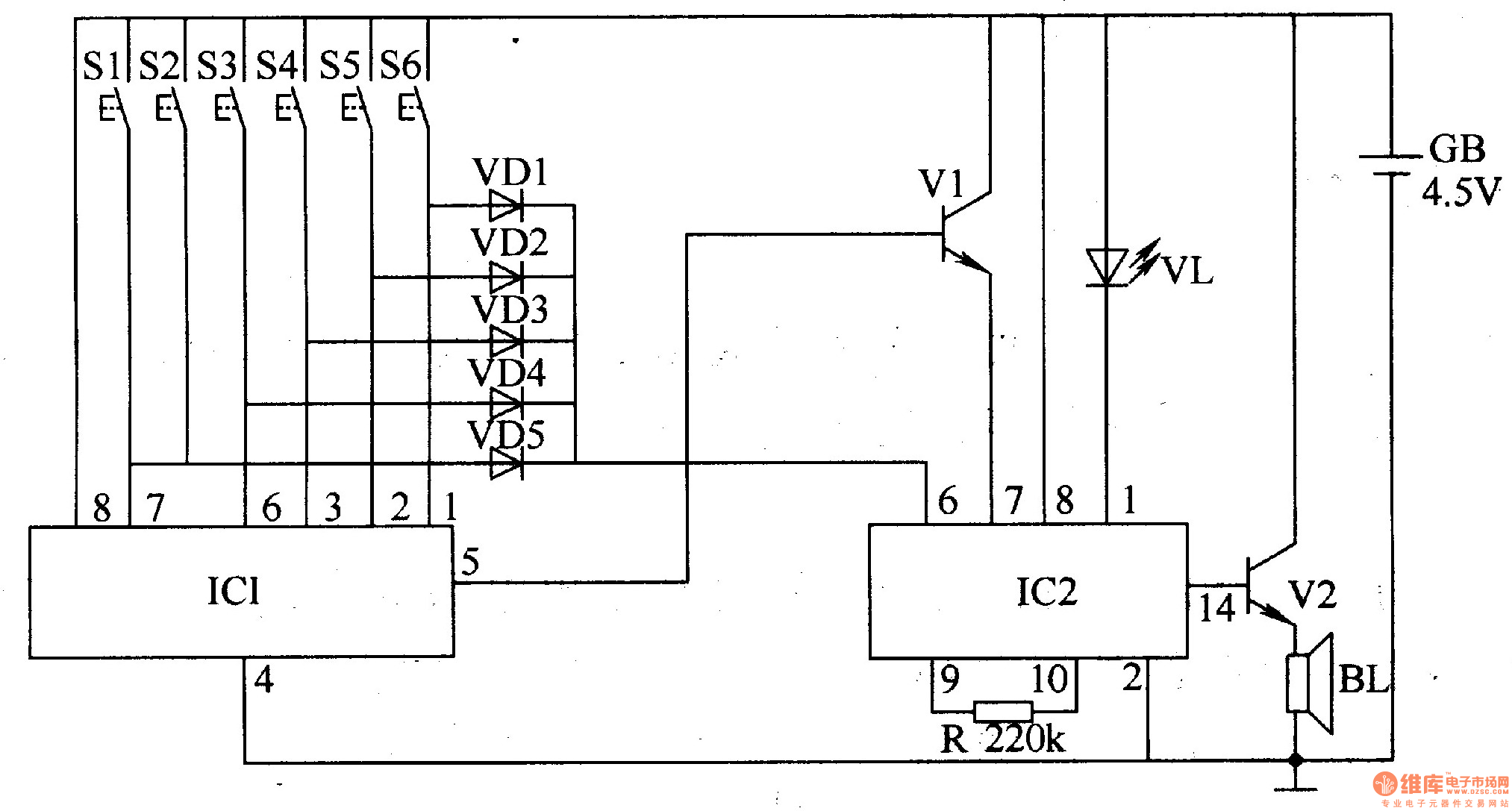
The electronic doorbell circuit utilizes a password mechanism and includes both an electronic password circuit and a music generation circuit, as illustrated in Figure 3-118. The electronic password circuit is comprised of integrated circuit IC1, keys S1-S6, and diodes...
The simple bell circuit without IC. It includes a doorbell circuit that can produce different sounds using integrated circuits, transistors, and resistors. The circuit utilizes a coded trigger mechanism to differentiate between various visitors. When the button is pressed,...