
Birdie Doorbell Circuit

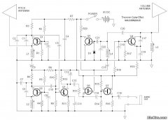
The doorbell circuit operates on a simple principle of sound generation through the use of a PNP transistor and a transformer. The circuit begins its operation when the user activates the push button (P1), which allows current to flow through the base of the NPN transistor, thus turning it on. This, in turn, activates the PNP transistor (T1), allowing current to flow through the transformer (L1) or battery, generating an audio signal.
The transformer (L1) plays a crucial role in this circuit. If a bell transformer is used, it typically converts the low voltage from the power source into a higher voltage suitable for driving the speaker. In cases where a battery is used, the diode (D1) ensures that the current flows in the correct direction, preventing damage to the circuit from reverse polarity. The choice of a general-purpose PNP transistor allows for flexibility in component selection, providing ease of replacement if needed.
The audio output is influenced significantly by the transformer (L2) sourced from an old AM radio. The characteristics of this transformer determine the frequency response and overall sound quality produced by the loudspeaker. Adjusting the values and types of transformers can lead to different sound outputs, allowing for customization based on user preference.
The loudspeaker must be capable of handling the power output of the circuit. An 8 Ohm speaker rated for at least 200 milliwatts ensures sufficient sound output without distortion. For optimal performance, a speaker rated at 2 watts is recommended, as it provides a better safety margin and improved sound quality.
In summary, this doorbell circuit design offers an innovative way to produce a bird-like sound using a combination of basic electronic components. The flexibility in component selection and the ability to customize sound output make it an engaging project for those interested in electronics.This is a design circuit for a doorbell. This circuit can produces a sound like bird sound. This circuit controlled by transistor NPN. This is the figure of the circuit. The operation of the circuit is beginning when P1 is of experimental value. Start with 220 Ohms or so and modify to suit your needs. The transistor is a general purpose kind and i s not critical, almost any PNP type will work. L1 is a bell-transformer which is usually already present in the house. If you wish, you could use a battery instead of the bell transformer. Just hookup a 9-volt battery (or wall adapter)to points `A` and `B` (A=+) the diode (D1) is to protect the circuit from accidental polarity reversal and is optional, but required as a rectifier for use with the bell transformer. T1 is a General Purpose PNP transistor and probably anything will work. L2 comes out of an old am transistor radio. They look like miniature transformers and are usually colored red or green. You have to fiddle with different transformers as the sound can vary depending on the value. The loudspeaker is a 8 Ohm type and must be larger than 200milli-Watt. I used a 2Watt type, but anything over 0. 2W will do. 🔗 External reference
Related Circuits
The PT2399 digital echo circuit schematic is an electronic design that utilizes the PT2399 integrated circuit (IC) for audio applications. This digital echo processor, based on CMOS technology, incorporates both analog-to-digital conversion (ADC) and digital-to-analog conversion (DAC) processes for...
The optical safety switch circuit includes a power supply circuit, a light control circuit, and a control implementation circuit (switch circuit). The power circuit is made up of a power transformer (T), a bridge rectifier (UR), and a filter...
Firecrackers are typically ignited using a matchstick or candle. After igniting the fuse, it is necessary to retreat quickly to a safe distance. This method poses safety risks due to the possibility of the firecracker detonating before reaching a...
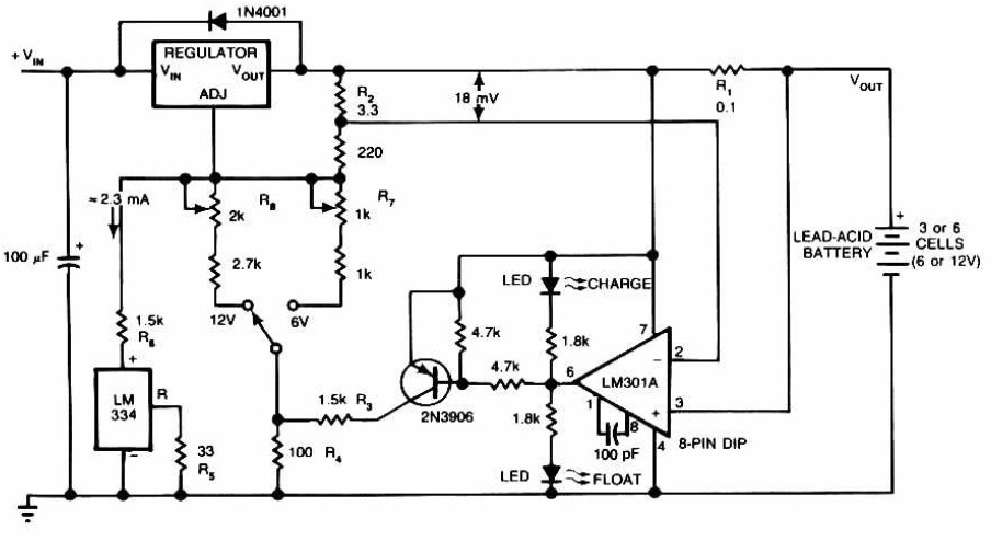
Lead-Acid Battery Charger circuit diagram. The LM301A compares the voltage drop across R1 with an 18 mV reference set by R2. The comparator's output controls the voltage regulator, forcing it to produce the lower float voltage when the battery-charging...

This design circuit is a tachometer circuit based on the LM2907 integrated circuit, which can provide zero-crossing data to a digital system. At each zero crossing of the input signal, the charge pump alters the state of capacitor C1...
A capacitance meter is an essential instrument for electronics hobbyists and professional electronic technicians. A capacitance meter is a specialized device used to measure the capacitance of capacitors in electronic circuits. It is a valuable tool for diagnosing and troubleshooting...