
Password electronic doorbell 2

The password electronic doorbell circuit operates by utilizing a trigger mechanism that responds to user input via buttons S1 to S9. Each button corresponds to a specific password, allowing for a unique identification method for doorbell activation. The trigger circuit employs four NAND gate Schmitt trigger ICs, which provide a stable output signal in response to the button presses. The Schmitt trigger configuration ensures that the circuit is less susceptible to noise and provides a clean transition between high and low states.
The external RC components, consisting of resistors and capacitors, are used to set the timing characteristics of the trigger circuit. This timing can determine how long the doorbell remains activated after a button is pressed, ensuring that the music playback does not terminate prematurely.
The music generating circuit is responsible for producing the sound output when the doorbell is activated. Integrated circuits IC2 and IC3 are typically configured as sound generators, which may use techniques such as waveform synthesis or playback of pre-recorded audio samples. The transistors in this section serve as amplifiers to drive the speaker, ensuring that the sound produced is loud enough to be heard clearly.
Overall, the design of this password electronic doorbell circuit emphasizes both functionality and user interaction, providing a modern approach to traditional doorbell systems while ensuring a user-friendly experience.The password electronic doorbell circuit is composed of the trigger circuit and music generating circuit, and it is shown in Figure 3-119. Trigger circuit is composed of the buttons S1-S9, four NAND gate Schmitt trigger integrated circuit IC1 and the external RC components.
Music generating circuit is composed of the integrated circuits lC2 and 1C3, transist.. 🔗 External reference
Related Circuits
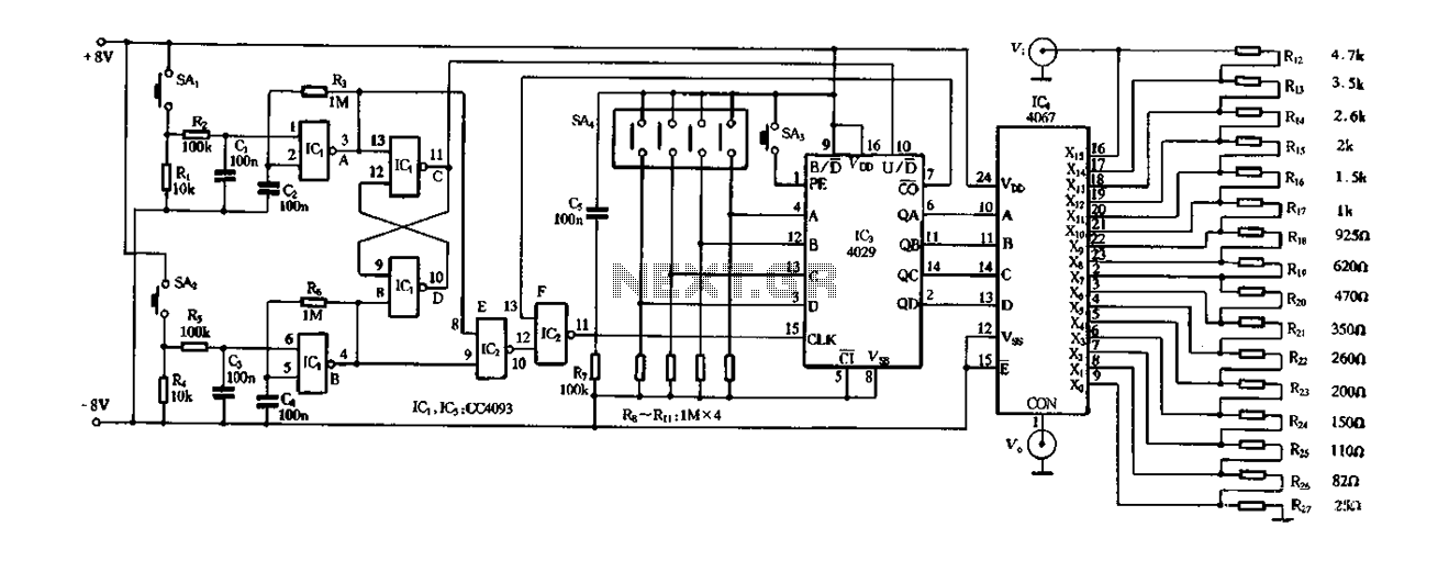
Figure 4-14 illustrates a digital integrated circuit featuring 16 preset potentiometers for Siniperca electronic circuits. The circuit comprises three main components: an input controller, a presettable counter, an analog electronic switch, and a resistor network. It includes a push-button...
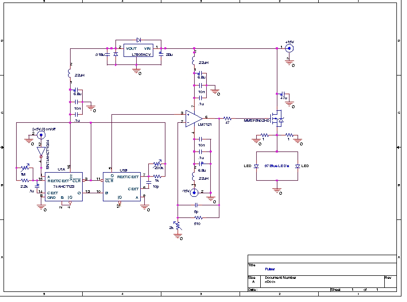
A Prototype Sample and Hold Circuit - The original concept for the veto front-end amplifiers was to continuously sample the input pulse height and maintain the pulse height for any pulses exceeding a low voltage threshold (approximately 10 mV)....
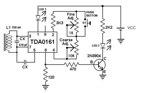
This metal detector circuit diagram utilizes the TDA0161 monolithic integrated circuit, which is designed to detect metallic objects by measuring variations in high-frequency Eddy current losses. The output signal is influenced by changes in supply current, which varies based...
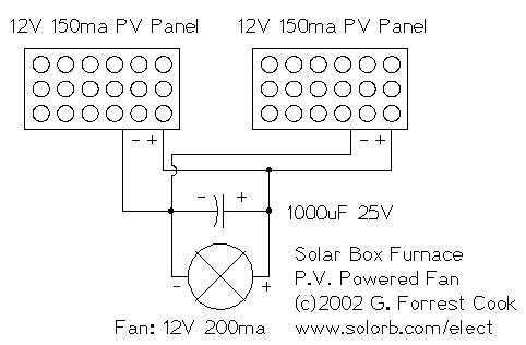
I decided to make a commercial surface mount PC board using the LED2 sensor concept. It is quite sensitive and can track to a few degrees of accuracy in bright sunlight. If a blocking shadow is used the accuracy...
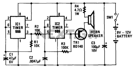
The oscillator based on IC2 generates sound, with its output connected to the base of TR1, which amplifies the signal to drive the speaker. Resistor R4 limits the current through TR1 to a safe level. The oscillation frequency of...
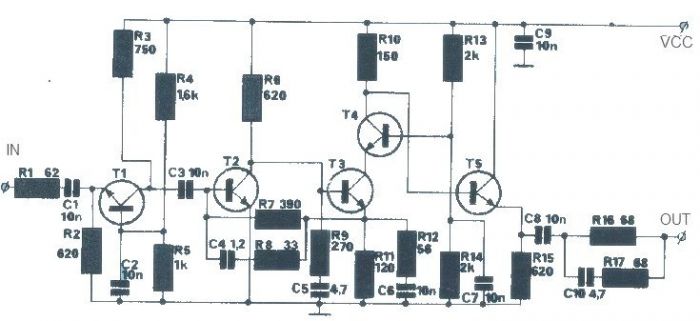
The T1 transistor must be of the BF200 type (or a similar variant), while the other transistors can be of the BF214 type. To achieve high efficiency, the antenna amplifier should be positioned at a short distance from the...