
double conversion pulse counting fm tuner
No description available.
Related Circuits
The boards are powered by two 9-volt alkaline batteries. The circuits are a compilation of those found in the Radio Shack Engineering Handbook for constructing pulse-modulated LED transmitters and receivers. The laser diode "D1" is replaced with an affordable...
This circuit functions as a missing pulse detector, utilized in the General Purpose Controller Board with Basic Stamp 1. It monitors an input pulse train, and when a pulse is missed, the output of the 555 timer switches to...
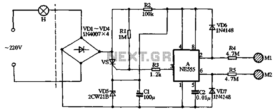
The circuit illustrated in the figure features a dashed line on the left, representing a standard lighting circuit, while the right side is responsible for the dual functionality of touch activation using the NE555 timer. Components VD1 through VD4...
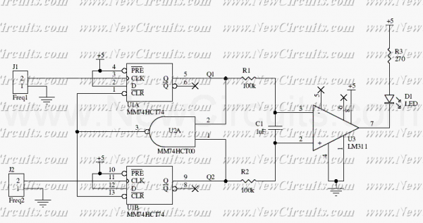
This circuit uses a 74HCT74, 74HCT00, and a LM311 to form a frequency comparator. The two pulse trains are fed to two D-type flip-flops (triggered by the leading edges). The flip-flops' outputs are compared in a NAND gate. If...
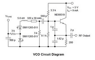
The high performance of modern set-top DBS TV tuners necessitates the development of broadband voltage control oscillator (VCO) designs that are cost-effective. Design engineers face the challenge of creating high-performance, low-cost VCOs. The traditional Colpitts oscillator design is commonly...
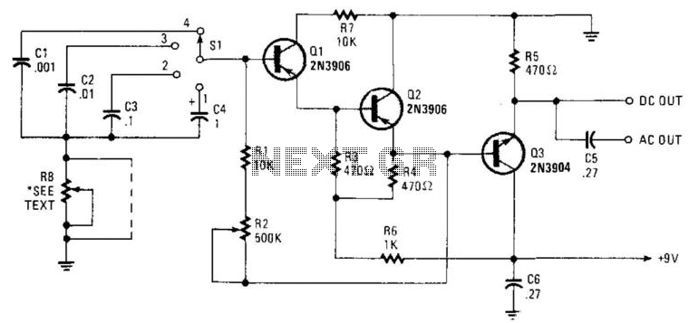
Seven narrow pulses ranging from 2 Hz to 50 kHz are generated by this circuit. Capacitors C1 through C4 provide frequency ranges in decode steps. Resistors R1 and R2 regulate the charging time of capacitors C1 through C4. R2...