
Double-ended limit detector

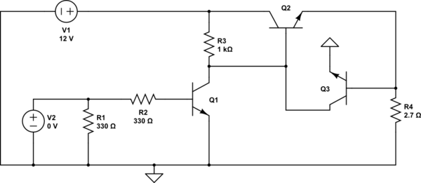
The circuit utilizes the L144 operational amplifier in conjunction with a CMOS NAND gate to effectively monitor voltage levels with minimal power consumption. The three sections of the L144 serve to amplify and process the input voltage, which fluctuates between ±10 V. This bipolar signal is transformed into a unipolar output ranging from 0 to 10 V through the use of four 1 MΩ resistors (R1, R2, R3, and R4).
These resistors are configured to create a voltage divider network that ensures the output remains within the acceptable range for the CMOS logic, which is referenced to ground. This design choice is crucial for maintaining compatibility with the digital logic levels required for subsequent processing stages.
The power dissipation characteristics of the circuit are noteworthy, with a total of 290 µW when the monitored voltage is within specified limits, indicating efficient operation under normal conditions. However, when the voltage exceeds the defined limits, the power dissipation increases to 330 µW, which may indicate a need for further analysis or additional protective measures in high-voltage scenarios.
Overall, this low-power voltage monitor circuit is suitable for applications where energy efficiency is paramount, and its design ensures reliable performance in monitoring voltage levels across a range of operational conditions.Detector uses three sections of an L144 and a CMOS NAND gate to make a very low power voltage monitor. The 1 MO resistors Rl, R2, R3, and R4 translate the bipolar ±10 V swing of the op amps to a 0 to 10 V swing acceptable to the ground-referenced CMOS logic
The total power dissipation is 290 µW while in limit and 330 /xW while out of limit.
Related Circuits
This simple circuit detects RF radiation leaking from transmitters, faulty connections, broken cables, or equipment with inadequate RF shielding. It is designed for the 2-meter amateur radio band (144-146 MHz in Europe). The instrument features a 4-step LED readout...
The second transistor (T2) is activated by the current passing through the resistor (R1). When a DALI slave unit is connected, this current matches the current flowing through the power transistor (T1). The resistor's value is selected so that...
A detailed discussion on implementing current limiting or foldback current limiting for the linear regulator controllers of the MAX1864. This can also be applied to other discrete regulator designs, including the MAX1865, MAX1964, MAX1965, MAX8513, and MAX8514. To incorporate current...
This circuit employs a 15-kHz oscillator coil. When metal is removed from the energy field, the oscillator voltage is rectified and compared to a reference. A decrease in oscillator voltage activates comparator IC2, causing D4 (LED) to turn off. L1...
A PIC microcontroller and an LCD have been integrated into a basic radiation detector, enabling the display of total counts over a 24-hour period or counts per second, as well as the relative gamma strike energy level. The energy...
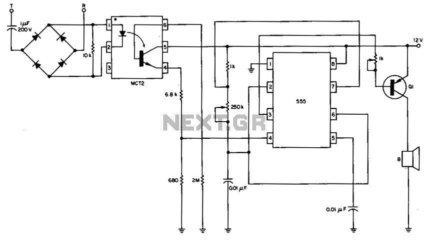
The 555 timer is configured as a multivibrator in conjunction with an opto-isolator to drive a remote speaker. The circuit utilizes the 555 timer in astable mode to generate a continuous square wave output. This output is then used to...