
Simple 144 MHz RF Detector

The RF radiation detector circuit operates by utilizing a simple yet effective design that integrates various components to ensure accurate detection of unwanted RF emissions. The antenna serves as the initial point of signal acquisition, capturing the RF energy emitted from nearby sources. The resonant circuit formed by capacitor C1 and inductor L1 is critical in tuning the circuit to the desired frequency range, allowing for optimal sensitivity to signals within the 2-meter band.
The rectification process is facilitated by diode D1, which converts the alternating current (AC) RF signal into a direct current (DC) signal suitable for further amplification. The two-transistor Darlington amplifier configuration (T2 and T3) significantly increases the gain of the rectified signal, ensuring that even low levels of RF radiation can trigger the LED indicators and the alarm system.
The 4-step LED readout provides a visual representation of the detected RF radiation levels, with each LED corresponding to a specific threshold of radiation intensity. This allows users to quickly assess the RF environment. The audible alarm, activated by the UM66 chip, serves as an additional alert mechanism, providing immediate feedback when high radiation levels are detected.
The flexibility of the circuit is enhanced by the adjustable zener diodes, which allow users to customize the sensitivity and response of the instrument according to specific requirements or operational conditions. Furthermore, the ability to modify the resonant network (C1 and L1) enables the circuit to be adapted for use in other frequency bands, making it a versatile tool for amateur radio operators and RF enthusiasts.
In summary, this RF radiation detector circuit combines straightforward design principles with practical functionality, making it an essential device for monitoring RF emissions and ensuring compliance with safety standards in various electronic applications.This simple circuit helps you sniff out RF radiation leaking from your transmitter, improper joints, a broken cable or equipment with poor RF shielding. The tester is designed for the 2-m amateur radio band (144-146 MHz in Europe). The instrument has a 4-step LED readout and an audible alarm for high radiation voltages. The RF signal is picked up by an antenna and made to resonate by C1-L1. After rectifying by diode D1, the signal is fed to a two-transistor highgain Darlington amplifier, T2-T3. When all LEDs light, the (optional) UM66 sound/melody generator chip (IC1) is also actuated and supplies an audible alarm.
By changing the values of zener diodes D2, D4, D6 and D8, the step size and span of the instrument may be changed as required. For operation in other ham or PMR bands, simply change the resonant network C1-L1. As an example, a 5-watt handheld transceiver fitted with a half-wave telescopic antenna (G = 3. 5 dBd), will produce an ERP (effective radiated power) of almost 10 watts and an e. m. f. of more than 8 volts close to your head. Inductor L1 consists of 2. 5 turns of 20 SWG (approx. 1 mm dia) enamelled copper wire. The inside diameter is about 7 mm and no core is used. The associated trimmer capacitor C1 is tuned for the highest number of LEDs to light at a relatively low fieldstrength put up by a 2-m transceiver transmitting at 145 MHz.
🔗 External reference
Related Circuits

The multifunction frequency meter is an instrument that can measure various parameters on a single display using an 8-digit 7-segment LED. The controls measure... The multifunction frequency meter is designed to provide accurate measurements of frequency, voltage, current, and other...
The schematic is very simple and includes, in addition to Nutchip, with its three driving transistor and LED, the radio receiver. The data come from the OUT pin of the receiver and enter the pin REMOTE remote control. The...
This portable, pocket-sized mobile transmission detector can detect the presence of an activated mobile phone from a distance of one and a half meters. The mobile transmission detector is designed for convenience and portability, making it an ideal tool for various...
The standard circuit will display directly in Hz (1MHz max), and there is a separate on board divider that will allow you to display directly in KHz (approx 40MHz max). Because the display reads directly in Hz or KHz...
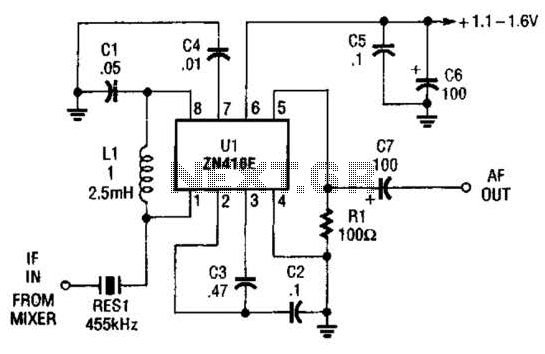
The ZN416E can be configured as a simple 455-kHz IF amplifier. In this case, the circuit's center frequency and bandwidth are set by RES1, which is a Murata CSB455E ceramic resonator. The ZN416E is a versatile integrated circuit designed specifically...
The circuit is designed for conducting safe experiments with high-voltage pulses and operates similarly to an electrified fence generator. This circuit is engineered to generate high-voltage pulses suitable for educational purposes and experimentation. The design is inspired by electrified fence...