
Double oscillator metal detector
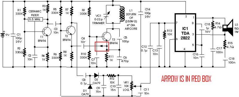
The described circuit features two oscillators operating at approximately 465 kHz, which are essential for generating a beat frequency signal. The first oscillator utilizes an IF transformer, while the second oscillator employs an inductor, specifically the search coil (LI). The coupling between the two oscillators is achieved through a 10 pF capacitor, allowing for interaction between the oscillators' outputs.
When the oscillators operate in close frequency proximity, a beat note is produced, which is a result of the interference between the two oscillation signals. This beat frequency is detected by a diode, which rectifies the signal, enabling it to be amplified by a headphone amplifier circuit. The output of the amplifier is then filtered through a 22 µF capacitor, which helps to smooth the audio signal before it reaches the headphones.
The search coil, which plays a critical role in the second oscillator, consists of 22 turns of enamel-coated wire. The wire can be of any gauge between 24 SWG and 36 SWG, providing flexibility in construction. The coil is center-tapped, which allows for balanced operation and improved sensitivity. The winding process involves using a temporary form, ensuring that the wire is neatly coiled and secured with tape and glue to a piece of hardboard, which serves as a stable base for the coil assembly. The dimensions of the coil are approximately 6 inches by 6 inches, which is a standard size for such applications.
The tuning of the search coil oscillator is accomplished using a variable capacitor with a range of 10-365 pF. This tuning capability allows for precise adjustments to the oscillator frequency, enabling the user to optimize performance based on specific operational requirements. It is important to note that the circuit is designed for high-impedance headphones, ensuring compatibility and optimal sound quality when listening to the output signal. Overall, this circuit design combines essential components to create a functional and effective oscillator system capable of producing and detecting beat frequencies.The circuit consists of two oscillators, both working at about 465 kHz. One uses an if transformer and the other uses an inductor (the search coil LI). The oscillators are coupled by a capacitor (10 pF). A beat note (produced if the two oscillators are working closely together) is detected by the diode and fed to the headphone amplifier and the 22 ?F capacitor. The search coil oscillator is tuned by a 10-365 pf variable capacitor. The search coil comprises 22 turns of wire (any gauge between 24 swg and 36 swg enamel) center tapped.
The wire should be wound on a temporary form then taped and glued to a piece of hardboard. The coil size should be about 6" ? 6". Headphones should be high impedance.
The search coil comprises 22 turns of wire (any gauge between 24 swg and 36 swg enamel) center tapped. The wire should be wound on a temporary form then taped and glued to a piece of hardboard. The coil size should be about 6" ? 6". Headphones should be high impedance.
🔗 External referenceRelated Circuits
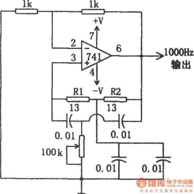
The circuit illustrated in the diagram is a 1 kHz sine wave oscillator circuit. Based on a double-T circuit configuration, it utilizes a standard 741 operational amplifier to generate a 1000 Hz sine wave output. The circuit begins oscillation...
A schematic diagram for a metal detector has been found. The project does not need to be original and can be sourced from the internet. There are several questions regarding this schematic. One query pertains to a small arrow...
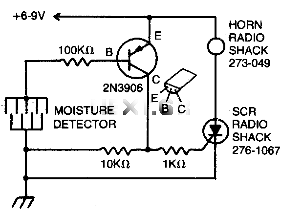
The detector consists of fine wires spaced approximately one to two inches apart. When the area between a pair of wires becomes moist, an alarm will sound. To deactivate the alarm, the DC power must be disconnected. The described moisture...
The Hartley Oscillator is characterized by an LC circuit in its collector. The base of the transistor is held steady, and a small amount of signal is taken from a tapping on the inductor and fed to the emitter...
This circuit relies upon the extra high input impedance of a FET, and also demonstrates the gate terminals sensitivity to changes in voltage. The gate terminal here is left open circuit, connected only to the "probe" this being just...
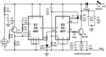
The following circuit illustrates an infrared toy car motor controller. This circuit is based on the 4047 and 4017 integrated circuits (ICs). Features: 16V. The infrared toy car motor controller circuit utilizes two primary integrated circuits, the 4047 and the...