
1kHz sine wave oscillator(741)
")
The described circuit employs a double-T oscillator topology, which is renowned for its simplicity and effectiveness in producing sine wave outputs. The heart of the circuit is the 741 operational amplifier, a widely used component in analog applications due to its versatility and availability. In this configuration, the operational amplifier is set up to provide necessary gain and feedback, which are crucial for sustaining oscillations.
The oscillation starts when the 100 kΩ potentiometer is adjusted, allowing fine-tuning of the circuit's threshold for initiating oscillation. The resistors R1 and R2 play a pivotal role in determining the frequency of oscillation. Their values, typically chosen for a 1 kHz output, must be carefully calculated to ensure that the circuit resonates at the desired frequency. The relationship between these resistors and the feedback network defines the oscillation frequency, following the formula for a double-T oscillator.
Additionally, the circuit may include capacitors in the feedback loop to stabilize the oscillation and filter any unwanted high-frequency noise. Proper selection of these capacitors is essential to maintain the integrity of the sine wave output. The output of the circuit can be connected to various loads, such as audio applications or signal processing circuits, where a stable sine wave is required.
Overall, this 1 kHz sine wave oscillator circuit exemplifies the fundamental principles of analog signal generation and can serve as a foundational design for more complex applications in electronic engineering.The circuit shown in the chart is 1kHz sine wave oscillator circuit. Basing on the double-T circuit, the circuit using 741ordinary operational amplifier to produce 1000Hz sine wave output. Adjusting 100k? potentiometer will make circuit start oscillation, the oscillation frequency is determined by R1 and R2, and under normal circumstances, the value of two..
🔗 External reference
Related Circuits
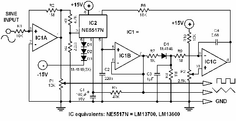
If a triangle wave signal or a square wave is required but only a sine wave generator is available, this converter can be utilized to simplify the process. The circuit consists of two integrated circuits (ICs): an LM13700 and...

Building a signal generator is an essential project for any analog DIY enthusiast. While already possessing a bench signal generator, the intention was to create a compact, battery-powered device for quickly testing new effect designs. An enclosure from a...
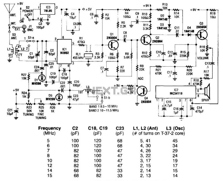
Using a Signetics NE602 in a varactor-tuned front end, the circuit of a shortwave receiver can be very simple and yet give high performance. This circuit also uses a ceramic filter as a sensitivity-determining device, two IF stages, AGC,...
Here is a simple triangle/squarewave generator using a common 1458 dual op-amp that can be used from very low frequencies to about 10 Khz. The time interval for one half cycle is about R*C and the outputs will supply...
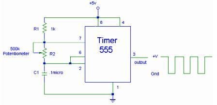
The setup for the Square Wave Generator can be initiated using a 555 timer IC as illustrated in the accompanying circuit diagram. It is essential to reference the pinout configuration of the 555 timer IC. An oscilloscope should be...
A Wien-bridge oscillator can be made variable by utilizing two frequency-determining components that are adjusted simultaneously with high tracking accuracy. However, high-quality tracking potentiometers or variable capacitors are often costly and challenging to procure. To circumvent the need for...