
Double IC For Circuit an Infrared Toy Car Motor Controller

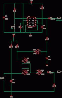
The infrared toy car motor controller circuit utilizes two primary integrated circuits, the 4047 and the 4017, to effectively manage the motor operations of the toy car. The 4047 IC functions as an astable multivibrator, generating a square wave output that can be used to control the speed of the motors through pulse-width modulation (PWM). This allows for variable speed control, which is essential for maneuvering the toy car smoothly.
The 4017 IC serves as a decade counter, which can be employed to control multiple outputs based on the clock pulses received from the 4047. By connecting the outputs of the 4017 to transistors or relay drivers, the circuit can activate or deactivate the motors in response to the infrared signals received from the remote control. This setup allows the toy car to move forward, backward, and turn, providing a full range of motion.
Powering the circuit at 16V ensures that both the 4047 and 4017 ICs operate efficiently while providing adequate voltage to drive the motors. Additional components such as resistors, capacitors, and diodes may be included to stabilize the circuit and protect against voltage spikes. The overall design emphasizes simplicity and effectiveness, making it suitable for educational purposes and hobby projects involving robotics and remote-controlled vehicles.The following circuit shows about Circuit an Infrared Toy Car Motor Controller. This circuit based on the 4047 and4017 IC. Features: 16V .. 🔗 External reference
Related Circuits
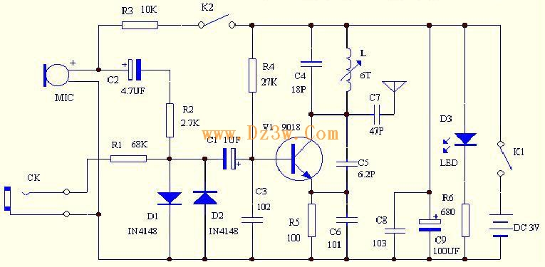
C4 and L form a resonator, where the resonant frequency corresponds to the FM transmitting power of the microphone. According to the component parameters in the diagram, the transmission frequency can range from 88 to 108 MHz. The frequency...
The Car Voltage Gauge is based on 3 parts. The input circuit is an Analog to Digital Converter (IC2 CA3162E). The purpose of this chip is to sample an analog voltage and convert it to a decimal value which...
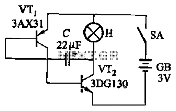
The circuit depicted in Figure 13-4 utilizes triode control. Two transistors, VTi and VTz, are coupled via a capacitor (C) to alternately turn on and off, producing a flashing light effect. The flash frequency is influenced by the capacitance...
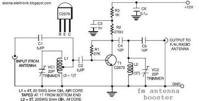
The coil L2 is tapped at the first turn from the ground lead side and is similar to coil L1, but consists of only three turns. The pin configuration of the transistor 2SC2570 is illustrated in the FM antenna...
This circuit is designed for an electrically operated rolling shutter, typically featuring a standard control panel with a three-position switch: up, down, and stop. To automate the opening and closing with a time-controlled switch, additional wiring connections are required....
This circuit is a simple -5V power supply using a 555 timer, designed for low-power analog applications involving FET operational amplifiers. The circuit converts +5V to -5V to create a dual power supply. It operates as a 555 astable...