
doubler voltage with ne555 schematic
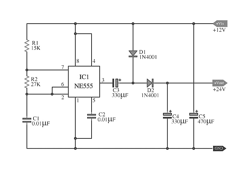
The circuit described utilizes an astable multivibrator configuration, which is a common method for generating square wave signals. The heart of this circuit is the integrated circuit (IC1), which is typically a timer IC such as the 555 timer. In this configuration, the timing components—resistors R1, R2, and capacitors C1 and C5—determine the frequency of oscillation. The output frequency can be calculated using the formula:
\[ f = \frac{1.44}{(R1 + 2R2) \cdot C1} \]
For this specific design, the values of R1, R2, and C1 should be selected to achieve the desired frequency of approximately 2 kHz.
The output signal from pin 3 of IC1 is a square wave that can be used for various applications such as clock signals, tone generation, or pulse width modulation. The capacitors C3 and C4, in conjunction with diodes D1 and D2, form a voltage doubling circuit. This circuit is designed to increase the voltage level to twice that of the input voltage, effectively providing an output of around 24 VDC.
The diodes D1 and D2 are crucial in this voltage doubling configuration, as they allow current to flow in one direction while blocking it in the opposite direction, ensuring that the capacitors charge correctly and discharge to the load as needed. The overall circuit thus serves a dual purpose: generating a stable square wave signal at 2 kHz and providing a higher voltage output suitable for powering other electronic devices or circuits.
Careful consideration should be given to the ratings of the components used, particularly the capacitors and diodes, to ensure they can handle the voltage and current levels in the application. Proper layout and grounding practices are also essential to minimize noise and ensure stable operation of the multivibrator and voltage doubling function.The capacitors C5 give with IC1, The resistor R1, R2 and, capacitors C1, Which build the circuit model astable multi vibrator Square wave generator, at the frequency about 2KHz come out the way pin 3 of IC1. By have capacitors C3, C4 diode D1 and D2. Which build be boost up voltage x 2, which will enhance the level Volt out be the direct current abo ut 24VDC or 2 times of the level Volt input. 🔗 External reference
Related Circuits

The schematic illustrates the design of a circuit that measures the resistance of the skin and transforms it into a functional switching signal. This circuit typically employs a resistive sensor, often referred to as a skin resistance sensor or galvanic...
Here are some schematics and information that can be difficult to locate elsewhere. If there are schematics that should be included in this collection, please feel free to reach out. The intention is to expand this collection over time,...
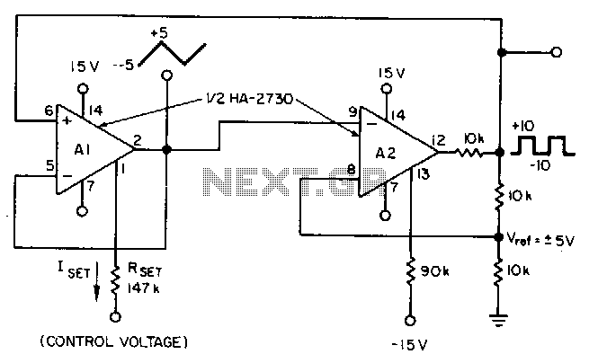
This circuit utilizes a programmable operational amplifier, specifically the HA2730, which is a two-amplifier monolithic chip featuring independent programming ports for each amplifier. The parameters of the amplifiers, including the slew rate, vary linearly based on a set current....
Many electronics hobbyists have encountered the situation where a project is being completed late at night and the mains supply fails. The cause of the failure, whether due to the electricity provider or personal oversight, is not significant. In...
C0QBmk~%24(KGrHqIOKkIEq4M%2Bu,)1BK2zHH580Q~~_35.gif)
This time, information will be shared about the schematics of radios, specifically the schematic of a programmer radio, along with the latest information available on Onmilwiki. The schematic of a programmer radio typically includes various components essential for its operation,...
A small Tesla Coil (12-inch range), Jacob's Ladder, or an "Antigravity Project" from the book "Electronic Gadgets for the Evil Genius" is being discussed, but sourcing parts for these projects has proven challenging. The book is informative, yet the...