
DRAG RACE TIMING SYSTEM

This drag race timing system employs a microcontroller to manage the timing and display of race results, showcasing the potential of low-cost electronics in complex applications. The microcontroller's core functions include tracking the elapsed time, calculating the average speed over a quarter-mile distance, and interfacing with various sensors and display units. The system's architecture integrates a series of components that work in tandem to ensure accurate timing and reliable operation.
The Christmas Tree light system serves as a visual cue for racers, providing clear signals for race initiation and completion. The fault sensor plays a crucial role in ensuring fair competition by preventing premature starts, thereby enhancing the integrity of the race. The finish line sensor is critical for stopping the timer accurately, ensuring that the recorded time reflects the actual race duration.
The choice of an HC11 microcontroller for this project is significant due to its balance of cost and functionality. With a modest memory capacity, it is capable of handling the necessary computations for timing and speed calculations. Additionally, the use of infrared relay sensors allows for non-contact detection, which is advantageous in a racing environment where physical barriers could impede performance.
The system's design accommodates flexibility in sensor choice, indicating that while Allen Bradley components were selected for their reliability, future iterations could utilize alternative sensors that may offer cost savings without sacrificing accuracy. The ability to switch between different sensor types without major redesigns illustrates the modularity of the system.
In summary, this drag race timing system exemplifies the effectiveness of microcontroller-based designs in managing complex tasks with precision and efficiency. The integration of various components, including visual indicators, fault detection, and accurate timing mechanisms, demonstrates the potential for such systems to be implemented in competitive racing environments, all while maintaining a budget-friendly approach.This system is a Drag Race timing system centered around a micro-controller. The system consists of the Christmas Tree (the three yellows, the green and red lights), the fault sensor (checks to see if a racer started racing before the green light), the finish line which stops the running timer, and the display (which shows the time). The micro-con troller is used to track the racers time final time, calculate the avg. speed for the 1/4 mile and then display it. The timing circuit is accurate to the hundredths of a second, and the speed display shows the avg. speed over the 1/4 mile track based upon the 1/4 mile time in whole miles/hour. To show that complicated systems can be controlled by inexpensive micro-controllers. This project was completed to prove the feasibility of a full blown drag race timing system being controlled by a simple micro-controller. If a processor with more memory was used for a full scale project a second lane could have easily been added.
This particular micro-controller and board costs less than $100. The sensors run about $200 per complete set. The AB sensor`s I used for this project do not necessarily need to be used. An equally accurate, and less expensive option would be advisable if this system were ever to go to production. These are readily available, but a different type of sensor would most likely be used on a full scale unit.
This demonstration display shows that a complicated system can be managed very accurately for less than $500. This project was built using an HC11 EVBU (Evaluation Board) with a Motorola M68HC11E9 52-Pin PLCC/CLCC Processor with the standard 512 bytes of EEPROM.
In addition to the HC11, two Allen Bradley sensing units were acquired. These specific units are not necessary for this project as other sensing options could be accommodated easily, however the AB units were chosen because they are robust and reliable. PORT E / 0 PIN 43 INDEXED AT = $01 ; LOGIC HIGH ON THIS PIN BYPASSES THE BUFFALO MONITOR PROGRAM ON RESET.
THIS PIN IS TO BE DRIVEN LOGIC LOW DURING PROGRAMMING, AND SWITCHED TO LOGIC HIGH DURING OPERATION. The sensors used in this system are Allen Bradley components. The sensing system is comprised of two AB infrared relay units. Attached to each of these units are two fiber optic leads. The emitting side of the sensor emits a infrared pulse down one of the two fiber optic leads. The second lead is connected to the receiver side of the AB unit. When the system is powered and the receiver is receiving the pulsed beam, the relay inside the AB switches. In our applications when the beam is detected a 5VDC or Logic High signal is sent to the HC11. When the beam is broken, the signal switches to 0VDC or Logic Low. The Switching time for the relay is 5 ms which is more than adequate for our needs. 🔗 External reference
Related Circuits
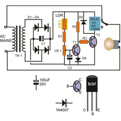
The left-hand side transistor T1 is configured as a voltage comparator utilizing a resistive network. The resistor in the upper arm is a light-dependent resistor (LDR), while the lower arm resistor is a preset resistor used to establish threshold...
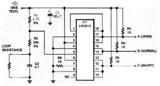
This security system is essential for homes, offices, and factories. It includes a circuit diagram that is simple and easy to construct, making it accessible for anyone. The circuit is cost-effective. Many security systems utilize a closed loop of...

A microprocessor-based home security system project. This advanced security system not only notifies the user but also alerts the police immediately. In the 8085 microprocessor-based home security system, control is exercised over a siren, telephone (via cradle and redial...
This timer circuit is similar to the 5 to 30 minute timer, but when switch S1 is closed, the on/off action of the circuit continues indefinitely until S1 is opened again. A 7555 timer and a low leakage capacitor...
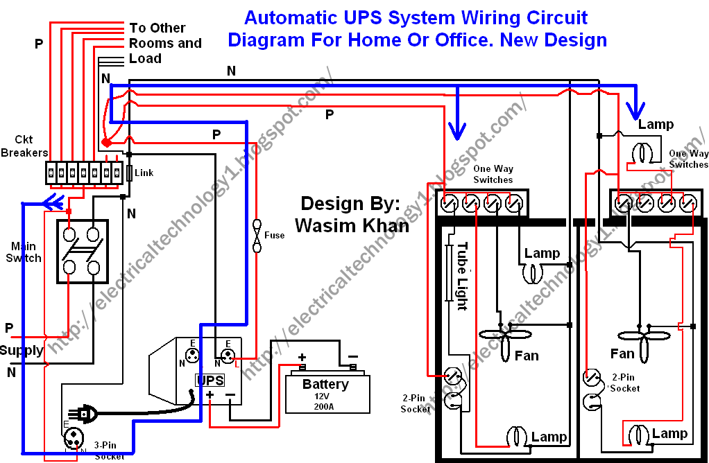
This wiring circuit diagram is designed for providing power to specific rooms in a home or office during a power supply failure. It ensures continuous power supply to devices such as laptops and computers in those particular rooms, especially...
This audio amplifier circuit is designed for use in classrooms to alleviate the strain of lecturing in noisy environments. It incorporates the power amplifier IC LM380, which delivers an output of 2 watts, adequate for confined spaces. The amplifier...