
Periodic Timer Timing

The timer circuit described utilizes a 7555 timer IC, which is a versatile component known for its reliability in timing applications. The configuration allows for continuous operation once activated by switch S1, making it suitable for applications requiring prolonged timing without manual intervention. The use of a low leakage capacitor for C1 is crucial, as it ensures minimal current loss, thereby enhancing the accuracy and stability of the timing intervals.
The 6-way rotary switch S3 serves as a means to adjust the timing duration by varying the resistance in series with the timing circuit. Each position of the rotary switch introduces a different resistance value, effectively altering the charge and discharge time of the capacitor C1. At the minimum resistance setting (point "a"), the circuit is designed to achieve a pulse duration of approximately 379 seconds, translating to just over 6 minutes. Conversely, at the maximum resistance setting (point "f"), the output pulse duration can extend to around 38 minutes.
The timing resistor chain, composed of resistors R1 through R6, plays a critical role in determining the overall timing characteristics. By selecting appropriate resistor values, the user can fine-tune the timing intervals to meet specific application requirements. Additionally, the output pulse at pin 3 of the 7555 timer can be utilized to drive various loads or trigger other circuits, making this timer versatile for different electronic applications.
Overall, this timer circuit design is effective for applications requiring long-duration timing with the flexibility to adjust timing intervals easily through the rotary switch. The combination of the 7555 timer and the adjustable resistor network allows for a broad range of timing capabilities, making it a valuable addition to any electronics project requiring precise timing control.This timer circuit is similar to the 5 to 30 minute timer except that when switch S1 is closed, the on/off action of the circuit will continue indefinitely until S1 is opened again. A 7555 time and low leakage type capacitor for C1 must be used. The 6 way rotary switch S3 adds extra resistance in series to the timing chain with each rotation, mini
mum resistance point "a" maximum point "f". The 7555 is wired as an equal mark/space ratio oscillator, the timing resistor chain R1 to R6, being connected back to the output of the timer at pin 3. The output pulse duration is defined as:- This gives on and off times of about 379 seconds for position "a" of S3 (just over 6 minutes), to about 38 minutes at point "f".
The times may of course be varied by altering R1 to R6 or C1. 🔗 External reference
Related Circuits
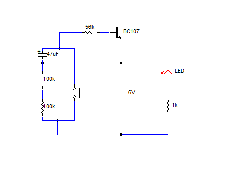
A simple transistorized one-minute delay timer circuit. It does not include any complex or critical components. This circuit can generate a time delay of approximately one minute. When the switch (preferably a push-button type) is pressed, the LED turns...
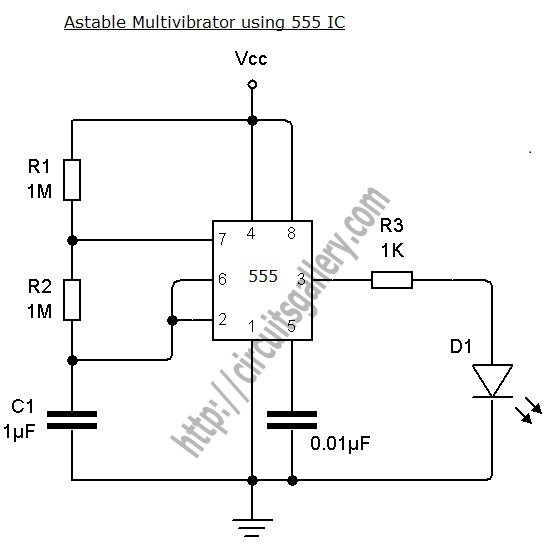
An astable multivibrator can be designed using a 555 timer IC, operational amplifiers, or transistors. The 555 timer IC provides accurate time delays ranging from milliseconds to hours, with the frequency of oscillation adjustable through simple modifications. This is...
Input values for R1, R2, and C, then press the calculate button to determine the positive time interval (T1) and negative time interval (T2). For instance, using a 10K resistor (R1) and a 100K resistor (R2) along with a...

The following circuit illustrates a practical electronics astable circuit diagram based on the 555 Timer IC. This circuit produces a pulse frequency of approximately 2Hz with a very low mark-space ratio, making it suitable for various applications. The single...
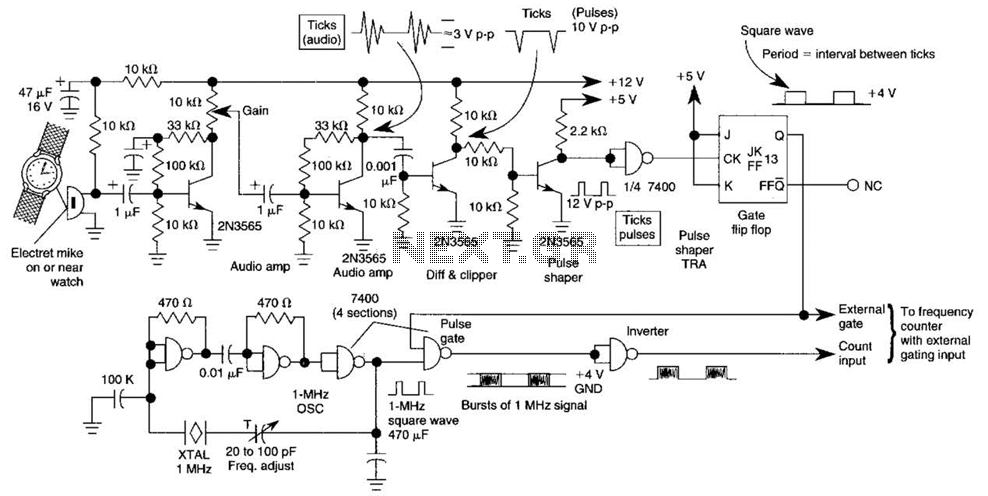
This circuit adapts a frequency counter to measure intervals. It was originally utilized as a shutter speed checker for photographic applications. The watch ticks are clipped, shaped, and formed into a square wave. This square wave is employed to...
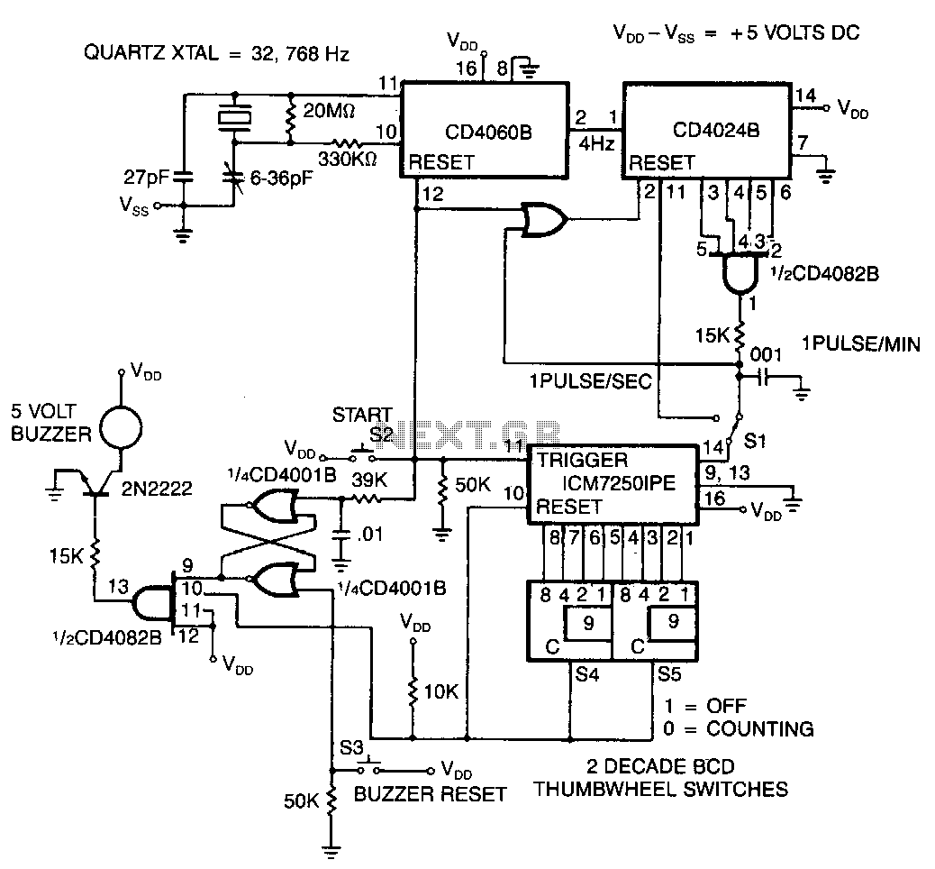
The time base is initially selected with switch S1 set for either seconds or minutes. Subsequently, values from 0 to 99 are chosen using the two thumbwheel switches S4 and S5. Finally, pressing switch S2 starts the timer. At...