
Microprocessor-based home security system

The complete circuit diagram of the microprocessor-based home security system is depicted in the accompanying figure. The transmitter section is designed around the timer IC NE555 configured as an astable multivibrator, followed by a transistor (T1) and an IR LED. The oscillation frequency of the transmitter is determined by resistors R1 and R2, a preset variable resistor (VR1), and capacitor C1. The output from pin 3 of IC1 is fed to the base of transistor T1 through resistor R3 for amplification, subsequently driving the IR LED. The modulated infrared signal is emitted by IR LED1 and directed at the base of the phototransistor. The output from the phototransistor is sent to transistor T3, followed by an operational amplifier (IC2) for signal amplification. The amplified signal is then provided to pin 3 of the Phase-Locked Loop (PLL) IC LM567 (IC3) through capacitor C4. The PLL IC functions as a frequency decoder in this context, facilitating load driving. The tuning frequency is set by variable resistor VR2 and a current-controlled oscillator using resistor R12. The tuning frequency (6-10 kHz) must align with the modulating frequency transmitted by the transmitter. Pin 8 of IC3 connects to the base of transistor T4 via resistor R13. An LED (LED1) illuminates to indicate that the receiving signal is synchronized with the transmitting signal.
Transistor T5 operates as a relay driver to energize relay RL5. Relay RL1 is normally energized when the transmitted IR signal reaches phototransistor T2, during which time the microprocessor does not receive any input. However, when the IR signal is interrupted, the microprocessor receives a high TTL-level signal through port A of the Programmable Peripheral Interface (PPI). The microprocessor initiates operations based on the commands stored in the EPROM (IC5) when it receives a high input from the PLL. An octal latch (IC6) interfaces between the low-order multiplexed address and latch lines AD0 through AD7 of the microprocessor (IC4) and the EPROM, allowing for the separation of address lines A0 through A7 from data lines D0 to D7 using the latch-enable signal (ALE). The high-order address lines A8 through A10 connect directly to the EPROM. The ALE pin (30) of the microprocessor connects to pin 11 of IC6. The output changes based on the input data when ALE is high; when ALE goes low, the lower-order address is latched at the output of IC6. Pins 18, 19, 20, and 25 of IC7 connect to the bases of relay driver transistors T6 to T9 through resistors R19 to R22, respectively. A high signal (indicating an interruption of the IR signal on the phototransistor base) energizes relays RL1 to RL4. A reset switch (SW1) is included in the design. The telephone line's polarity reversal is implemented using optocoupler ICs (IC8 and IC9). In a typical scenario, the TIP of the telephone set is positive compared to the Ring LED of the telephone line. When the handset is in the OFF-HOOK position, a loop current of approximately 10 mA flows through the telephone line. The polarity reversal from the DC line causes the internal LED of IC8 to conduct, which triggers the necessary alert mechanisms.A microprocessor based project Microprocessor-Based Home Security System . This advance security system not only let you know but also alert police immediately. In the project 8085 microprocessor based home security system we can control siren, telephone (via cradle and redial switches) and cassette player (alert message is recorded already) The mechanism of the project Microprocessor Based-Home Security System is very simple. As this project is IR based, the IR ray from transmitter is focused in the base of phototransistor of receiver fitted in opposite to each other. The property of phototransistor is that whenever the IR ray focused on its base is obstructed, the microprocessor as per program burnt in EPROM which further control siren, telephone and cassette player.
Hardware: The complete circuit-Diagram of Microprocessor Based Home Security System is shown in figure 1. The transmitter section is designed and fabricate around timer IC NE555 wired as astable multivibrator followed by transistor T1 and IR LED.
The oscillated frequency of transmitter section is decided by resistor R1 and R2, preset VR1 with capacitor C1. The output from pin 3 of IC1 is given to base of transistor T1 through resistor R3 for amplification as per required and given to IR LED.
The modulated IR signal is transmitted by IR LED1. The IR transmitted signal is focused on the base of photo transistor. The output from photo transistor is given to transistor T3 followed by op-amp (IC2) for amplification. The amplified signal from IC3 is given to input pin 3 of Phase-Locked-Loop (PLL) IC LM567 (IC3) through capacitor C4.
The normal use of PLL IC (IC3) is frequency decoder so is here in order to drive the load. The tuning frequency is determined by variable resistor VR2 and current controlled oscillator by resistor R12. The tuning frequency (6-10 KHz) should match with modulating frequency transmitted by transmitter. Pin 8 of IC3 is connected to base of transistor T4 through resistor R13. Glowing LED1 indicate receiving signal is locked to transmitting signal. Transistor T5 is used as relay driver in order to energize the relay RL5. Relay RL1 energized normally when transmitted IR signal falls on phototransistor T2, at this time microprocessor does not get any input.
But when IR signal is interrupted microprocessor get high (TTL-level) signal through port A of Programmable Peripheral Interface (PPI). The microprocessor start working as per command loaded in the EPROM (IC5) when high input is given from PLL.
Octal latch (IC6) is used for interface between low-order multiplexed address and latch lines AD0 through AD7 of microprocessor (IC4) and EPROM in order to separate Address line A0 through A7 from data line D0 to D7 by latch-enable signal (ALE), while high-order address lines A8 through A10 is directly connected to EPROM. ALE pin (30) of microprocessor is connected to pin 11 of IC6. The output changed according to input data when ALE is high, if ALE goes low the lower-order address is latch at the output of IC6.
Pin 18, 19, 20 and 25 of IC7 are connected to base of relay driver transistor T6 to T9 through resistor R19 to R22 respectively. The high signal (interrupt of IR signal on the base of phototransistor) on these pin energizes the relay RL1 to RL4.
For reset switch SW1 is used. Polarity reversed in the telephone line is build around optocoupler ICs (IC8 and IC9). As we all know that normal TIP of telephone set is positive in compare to Ring LED of telephone line. When the handset is in OFF-HOOK position, a loop current of 10mA is assumed for flowing in telephone line.
When the polarity reversed occurs from DC line the internal LED of IC8 conduct which 🔗 External reference
Related Circuits
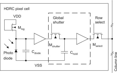
The initial section of this document outlines the high dynamic range CMOS (HDRC) imager, a specialized type of CMOS image sensor characterized by its logarithmic response. The significant capabilities of high dynamic range (HDR) image acquisition are explained through...
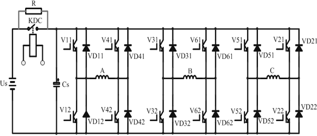
With the continuous growth of global vehicle production and ownership, the problems associated with vehicles are becoming increasingly apparent, particularly in China. Consequently, the development of zero-emission electric vehicles has emerged as a primary scientific research focus for many...
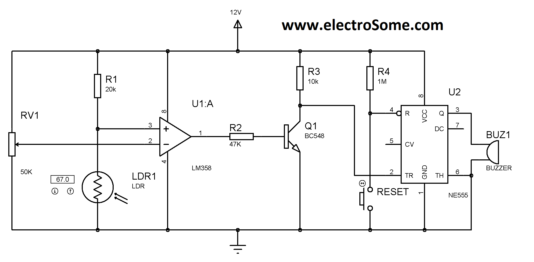
A simple and affordable laser-based security system, costing less than Rs. 100. This circuit utilizes an LM358 operational amplifier and an LM555 timer. It is activated when the laser beam is interrupted by a light-dependent resistor (LDR), which triggers...
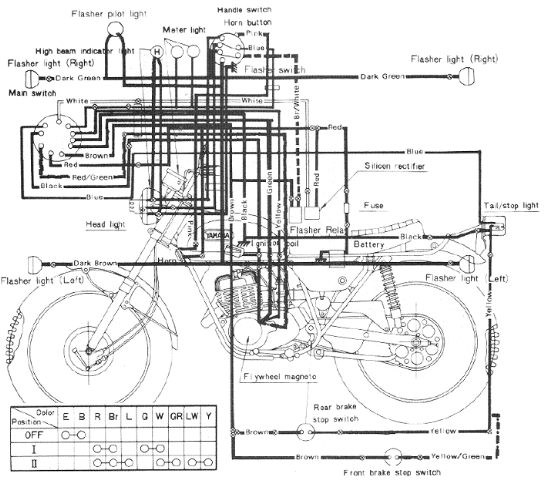
The following image illustrates the Yamaha 175 Wiring Diagram (CT2 and CT3 model) and Electrical System Schematic. It provides detailed information regarding the interconnection and wiring between electrical components of the motorcycle, including the battery, ground, headlight, taillight, horn,...
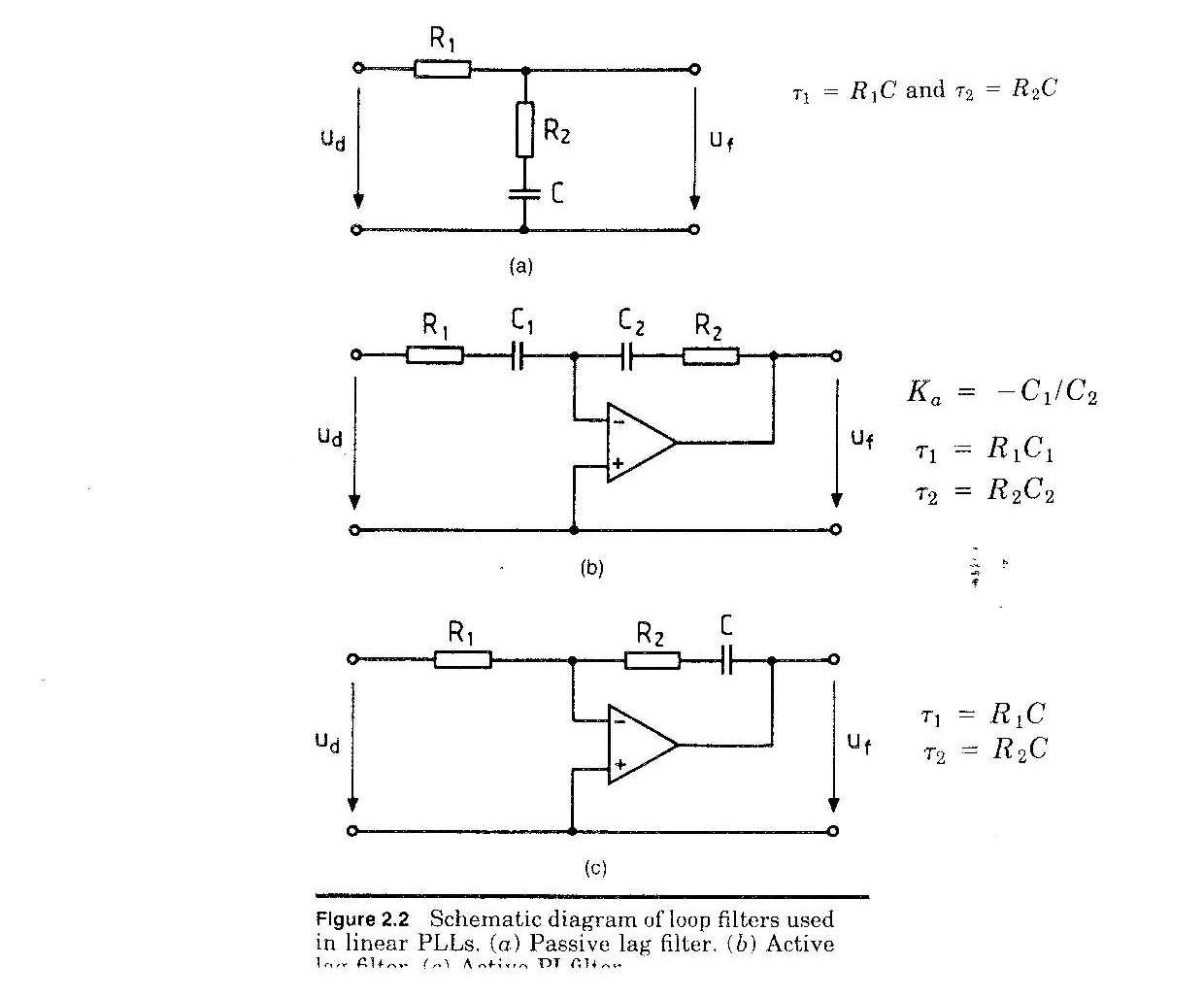
The phase-locked loop (PLL) is a crucial component in maintaining order in various electronic systems. For instance, in an analog television set, a PLL ensures that the image remains stable, keeping the heads at the top of the screen...
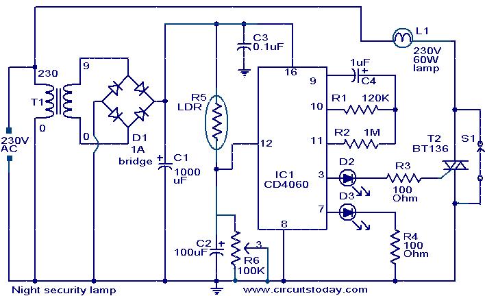
This simple circuit activates a light approximately two hours after midnight, a time when many robberies occur. The circuit is based on a CMOS IC 4060 to achieve the necessary timing. During the daytime, the light-dependent resistor (LDR) has...