
Drinking fountains automatic control circuit diagram
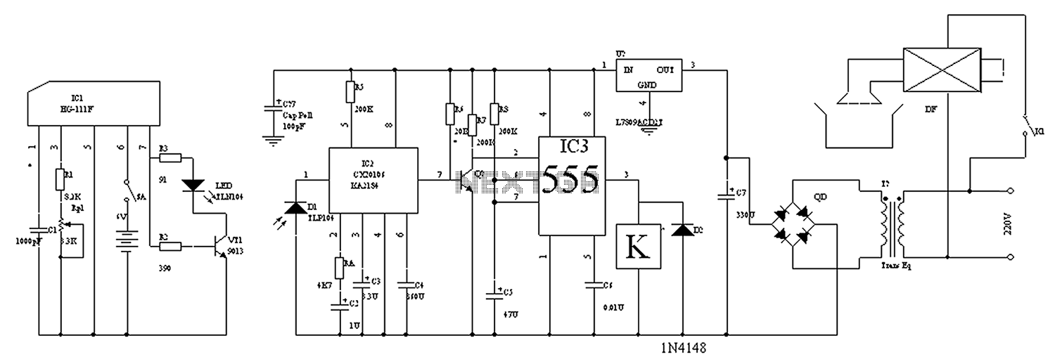
The automatic control circuit for drinking fountains typically employs a combination of sensors and control elements to manage the operation of the fountain efficiently. The main components of this circuit include a water level sensor, a microcontroller or timer, a relay, and a power supply.
The water level sensor is responsible for detecting the presence of water in the fountain reservoir. This sensor can be a float switch or a capacitive sensor, which provides an output signal when the water level falls below a predetermined threshold. The microcontroller processes the sensor data and determines whether to activate the fountain.
When the water level is low, the microcontroller sends a signal to the relay, which in turn activates the water pump to refill the fountain. The relay serves as an interface between the low voltage control circuit and the higher voltage pump circuit, ensuring safe operation.
Additionally, the circuit may include a timer function to prevent the pump from running continuously, allowing for programmed intervals of operation. This feature helps conserve water and energy while ensuring the fountain remains functional.
The power supply for the circuit must be adequately rated to support both the control electronics and the pump. Proper circuit protection, such as fuses or circuit breakers, should also be incorporated to safeguard against overloads.
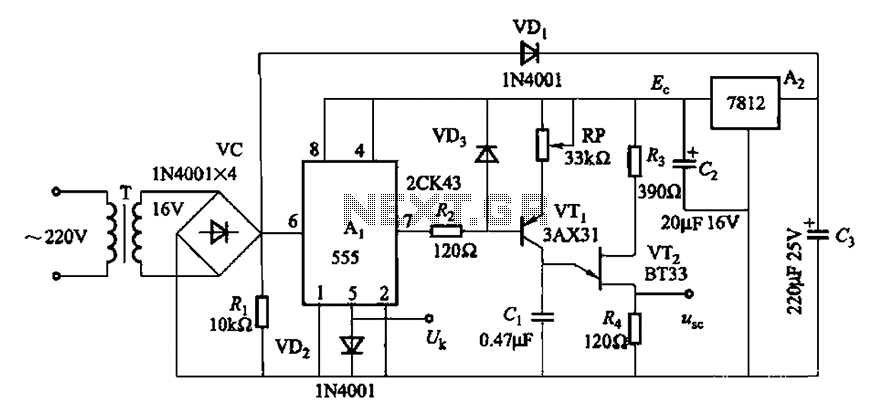
Overall, the automatic control circuit for drinking fountains enhances user convenience and promotes efficient water usage, making it an essential design for modern drinking fountain systems.Drinking fountains automatic control circuit diagram as follows:
Related Circuits
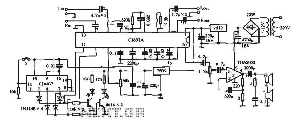
The surround processing section C1891A is a product from Sony Corporation of Japan that features a four-dimensional home theater surround processing circuit. It includes a parent roll phase-shifting circuit and a matrix surround sound amplifier. Additionally, it provides three...
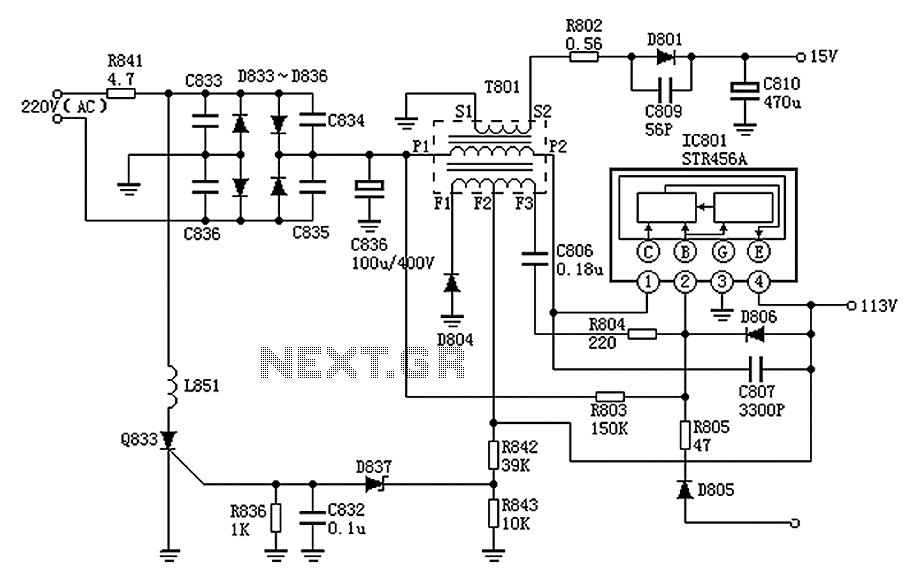
The Panasonic M12H switching power supply circuit is utilized in Panasonic models such as TC-230H, TC-2030DHN, TC-830D, and TC-840D. The circuit operates with an oscillation frequency that generates approximately 300V DC voltage at C836. The T801 transformer is involved...
While developing an infrared (IR) extender circuit, a method was required to measure the relative intensities of different infrared light sources. This circuit is the culmination of that research. It utilizes a photodiode, specifically the SFH2030, as the infrared...
Both circuits can synchronize trapezoidal wave voltage, which is converted into intermittent small rectangular pulses. Its working principle involves periodic operation in synchronization with the grid frequency of the zero-volt switching voltage of the DC chopper. Due to the...
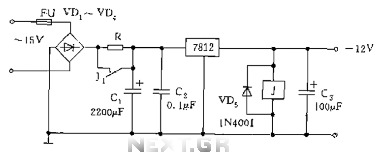
The figure below illustrates the use of a relay in the starting circuit. The power input connects through a resistor R, which serves two purposes: first, it prevents a large current from the capacitor C1 from affecting the power...
The humidifier circuit is based on a specific humidity sensor, Type NH-3 from Figaro. The circuit controls a ventilator that is part of an air humidifying system, depending on the sensor output. A triac is used to switch the...
Warning: include(partials/cookie-banner.php): Failed to open stream: Permission denied in /var/www/html/nextgr/view-circuit.php on line 713
Warning: include(): Failed opening 'partials/cookie-banner.php' for inclusion (include_path='.:/usr/share/php') in /var/www/html/nextgr/view-circuit.php on line 713