
Drive an RGB led with software PWM

The electronic schematic for this project involves the integration of an ATTiny microcontroller, RGB LEDs, and a push-button switch. The ATTiny microcontroller is configured to utilize an 8MHz clock signal from the internal RC oscillator, with appropriate fuse settings adjusted to ensure optimal performance. The microcontroller's output pins are connected to the RGB LED, allowing for independent control of each color channel through PWM. Each channel is driven by a dedicated 8-bit counter, which is incremented by an overflow interrupt from the hardware timer. The PWM duty cycle for each channel is adjusted periodically to create a smooth transition of colors.
The button switch is connected to an interrupt pin on the microcontroller, enabling immediate response to user input. Software debouncing is implemented to ensure reliable button presses. The circuit may include current-limiting resistors for the LED channels to prevent excessive current flow, enhancing safety and prolonging component life.
Power supply options include the use of alkaline batteries or lithium cells, with a voltage regulator employed as necessary to maintain a stable operating voltage for the ATTiny microcontroller. The entire circuit can be prototyped on a breadboard for initial testing, with the possibility of developing a compact PCB layout in the future. This project exemplifies the application of microcontroller technology in creating interactive and visually engaging electronic displays.This project illustrates how to use an ATTiny microcontroller and an RGB LED to create a coloured light that cyles continuously through random colours, but changes colour dramatically at the press of a switch. Why My kids had this $2 novelty pen that did this employing a teensy circuit along with 3x3mm LEDs and some alkaline coin-cells.
If children will play with this, choose one of the following: ensure your LED is not a superbright, or use a diffuse led, or diffuse a clear one (eg cover it with half a table tennis ball, or enclose it in resin or wax. You could also use higher-value resistors to limit current, or lower PWM_OC_MAX to limit the PWM duty-cycle (LED brightness) via software.
The microcontroller should be configured to obtain the system clock from the 8MHz internal RC oscillator. The ATTiny13 factory fuse settings include a divide-by-8 of the RC oscillator giving 1MHz, so remember to change that fuse to get the original 8MHz signal.
The overflow interrupt from the hardware 8-bit timer triggers an interrupt service routine (roughly 32000 times per second) which increments each of 3 separate 8 bit counters. These counters, and corresponding "Output Compare" (OC) values are used to generate 3 Pulse-Width-Modulated waveforms, with each counter being associated with a particular output pin.
Every time a counter reaches zero, the corresponding pin is turned on. When the counter reaches its PWM_OC value it is turned off. When the counter reaches its PWM_TOP value (255) it wraps around to zero and the cycle repeats. The effect of all this is that each of the 3 output pins is driven with a square-wave having a wave-legnth of 256 timer ticks (about 1/128 of a second), which is equivalent to a frequency of 128Hz (cycles-per-second). The OC value controls the "duty-cycle" (ratio of on-period to off-period) of the wave, with 0 giving always off, 255 always on, and any intermediate value giving a wave that is on for x/255 of a cycle and off for the remainder of each cycle.
If an electric light is powered by such a square wave, with a frequency of more than about 50Hz, the human eye does not percieve any flickering-instead changes in the duty cycle are perceived as changes in brightness (this is how most household dimmers work). With 3 leds in Red, Green and Blue, and the ability to vary the perceived brighness of each, you can produce many different colours, exactly as is done in modern TVs and projectors.
So using 3 PWM outputs, we have a coloured light that we can set to any brightness and colour (denoted by a particular [R=x, G=y, B=z] tuple) that we desire. BTW, it`s not strictly necessary to use 3 separate counters. A single counter could be used with 3 different OC values to control each output pin independently. I chose to implement 3 distinct channels (rather than 1 channel with 3 Output-compare values) out of some voodoo idea that running the channels out-of-phase will lower the peak current draw and give slightly longer battery life.
For example, if you set PWM_TOP to 240 and PWM_OC_MAX to 80, then if the PWM counters are initialized at 0, 80 and 160, the 3 output pins will never be on simultaneously, and peak output current will never be more than 20mA. This also means you can get away with ONE resistor instead of 3. For each of the 3 channels, at the end of every PWM cycle (when the counter reaches 255), the duty cycle of the particular channel changes by a small amount.
This causes the colour to change. The rate that each of the PWM channels changes duty-cycle is chosen semi-randomly such that an ever changing progression of colour is produced. If the CHANGE button is pressed, the LEDs are reset to all off (OCx=0), and the cycle-rate of one channel is changed to a new random value, giving an abrupt change of colour, followed by a new and different progression of colour changes.
Small children love this and will sit and frob the button for ages, before they break it or lose it. Then you can make them something else. Both buttons trigger interrupts via the pin-change interrupt facility. The buttons are "debounced" in software, by masking further interrupts for a certain interval after any button interrupt. I prototyped this on a solderless breadboard, and programmed the ATTiny with an AVRUSB500v2 programmer, which has the useful advantage of using a 1x5 connector instead of the more common 2x3 or 2x5, allowing simple in-circuit programming of breadboarded AVRs.
You can use any simple voltage regulator (or none). The ATTiny chips come in a 5v version that runs to 20MHz, or a low voltage version that will work off as low as 1. 8v (but is limited to 4 or 10MHz). I used an LP2950 low-dropout regulator, which will easily give you 5v from 4 alkaline cells, or 3. 3v from 3 cells. If you`re using a 9v battery, the cheap and common 78L05 (which needs an input of at least 7 volts) works fine too.
You could even leave the regulator off entirely, if you use a 4. 5v alkaline pack or a 3. 7v lithium. The low-votage ATTiny13v is remarkably forgiving (but remember to set the brown-out fuses to an appropriate low-voltage cutoff). I haven`t bothered to design a PCB yet, as it wouldn`t be significantly more compact than the protoboard version.
I suppose an SMD version would be interesting-it could be made not much larger than the coin cells that power it, giving some interesting swallowing-hazard fun to be had. 🔗 External reference
Related Circuits
Designs for audio amplifiers with DC coupling to the load are not frequently seen today, despite offering distinct advantages. Audio amplifiers that employ DC coupling to the load provide several benefits that can enhance performance in specific applications. In traditional...
This circuit is a small digital roulette. It is constituted by oscillator IC1, the counter IC2, the transistors Q1-7 that drive the display common cathode DSP1. The supply basically becomes from a battery 9V, but can become also from...
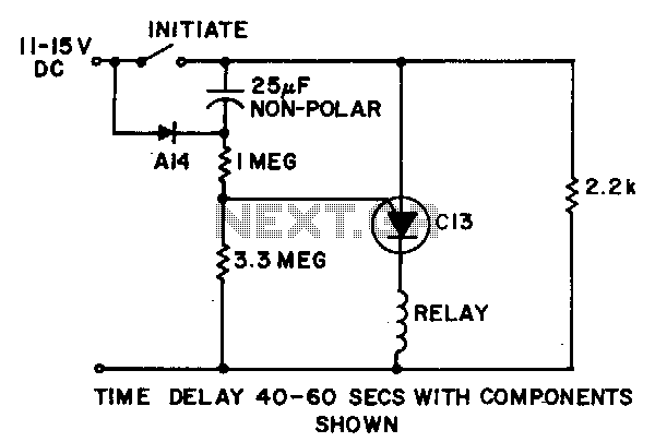
Power is applied to the circuit with the initiate switch open. The 25 µF capacitor charges through the A14 diode, or an equivalent, and a 2.2 kΩ resistor to the full supply voltage. When the initiate switch is closed,...
This circuit serves as an introduction to pulse-width modulation experimentation, utilizing a dual 555 timer for simplicity. A small PCB has been designed to facilitate construction. Although not an original design, it complements the "Dimmer with MOSFET" article on...
If you plan to use this circuit with a 110V 60Hz supply instead of a 230V 50Hz supply, or if you intend to modify this circuit, please refer to the section titled "Common Questions about this Circuit" found below...

These circuits are commonly utilized in robotics to enable DC motors to operate in both forward and reverse directions, as well as to provide an electric brake (short circuit condition). H-bridges can be found as integrated circuits or can...