
PWM Modulator

The circuit employs a dual 555 timer configuration, which is a versatile approach for generating pulse-width modulation signals. The first timer is set up in astable mode, continuously oscillating and generating a square wave output. The frequency of oscillation can be adjusted by varying the resistors R1 and R2, along with the capacitor C1, allowing for fine-tuning of the output signal to match the desired application. The choice of a frequency of 500 Hz is strategic, as it minimizes electromagnetic interference, making it suitable for controlling lighting applications.
The second timer, configured as a monostable multivibrator, serves to modulate the width of the output pulse based on the input trigger from the differentiator circuit formed by R3 and C3. This setup ensures that the output pulse width can be varied by adjusting the potentiometer P1, which modifies the voltage at the CNTR input. This voltage adjustment impacts the timing of the internal comparators, thereby influencing how quickly the capacitor C4 charges, which directly correlates to the output pulse width.
The design incorporates a protection mechanism via resistor R8 to safeguard against potential short circuits, ensuring reliability during operation. Additionally, the circuit's current consumption remains low, approximately 30mA, making it efficient for various applications, including dimming lamps via an opto-coupler. The range of control voltages provided by the potentiometer and the limiting resistors allows for a smooth transition of the output signal, enhancing the dimming capabilities without abrupt changes in intensity. Overall, this circuit design exemplifies a practical and efficient approach to implementing pulse-width modulation using widely available components.If you ever thought of experimenting with pulse-width modulation, this circuit should get you started nicely. We`ve kept simplicity in mind and used a dual 555 timer, making the circuit a piece of cake. We have even designed a small PCB for this, so building it shouldn`t be a problem at all. This certainly isn`t an original circuit, and is here ma inly as an addition to the Dimmer with MOSFET` article elsewhere in this website. The design has therefore been tailored to this use. A frequency of 500 Hz was chosen, splitting each half-period of the dimmer into five (a low frequency generates less interference). The first timer is configured as a standard astable frequency generator. There is no need to explain its operation here, since this can easily be found on the Internet in the datasheet and application notes.
All we need to mention is that the frequency equals 1. 49 / (R1+2R2) G— C1) [Hz] R2 has been kept small so that the frequency can be varied easily by adjusting the values of R1 and/or C1. The second timer works as a monostable multivibrator and is triggered by the differentiator constructed using R3 and C3.
The trigger input reacts to a rising edge. A low level at the trigger input forces the output of the timer low. R3 and C3 have therefore been added, to make the control range as large as possible. The pulse-width of the monostable timer is given by 1. 1xR4xC4 and in this case equals just over a millisecond. This is roughly half the period of IC1a. The pulse-width is varied using P1 to change the voltage on the CNTR input. This changes the voltage to the internal comparators of the timer and hence varies the time required to charge up C4. The control range is also affected by the supply voltage; hence we`ve chosen 15V for this. The voltage range of P1 is limited by R6, R7 and R5. In this design the control voltage varies between 3. 32V and 12. 55V (the supply voltage of the prototype was 14. 8V). Only when the voltage reaches 3. 51 V does the output become active, with a duty-cycle of 13. 5 %. The advantage of this initial quiet` range is that the lamp will be off. R8 protects the output against short circuits. With the opto-coupler of the dimmer as load, the maximum current consumption of the circuit is about 30mA.
🔗 External reference
Related Circuits
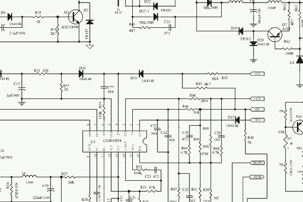
This document contains the datasheet and the circuit diagram of a PC Switching Power Supply utilizing the IC CG8010DX16. The CG8010DX16 is a highly integrated switching power supply controller designed for use in personal computer power supplies. It features a...
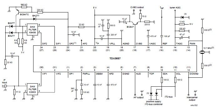
The integrated circuit (IC) is a multistandard vision and sound intermediate frequency (IF) phase-locked loop (PLL) demodulator that operates without the need for alignment. It supports multiple television standards, including PAL, SECAM, and NTSC, and is capable of handling...
Connecting and programming the TA8050 DC motor controller with the Arduino microcontroller. The TA8050 is a versatile DC motor controller designed for use with microcontrollers, such as the Arduino. This controller allows for precise control of DC motors, making it...
This circuit employs two signal generators to simulate an amplitude-modulated RF carrier wave. The output can be utilized to analyze the response of LC and tank circuits. One signal generator represents a high-frequency RF carrier at 200 kHz (VG2),...
The advantages of synchronous reception of AM signals are well recognized, including high selectivity, linearity of detection, and a lower noise level at the output compared to other reception methods. The circuit diagram is illustrated in Figure 1. The...

Here is a design circuit for a frequency modulator that is equipped with a tuning circuit. In this circuit, a pair of 1N4007 diodes is utilized as varactor diodes. The choice of 1N4007 diodes is not due to their...