
DTL integrated circuit by a crystal oscillator a
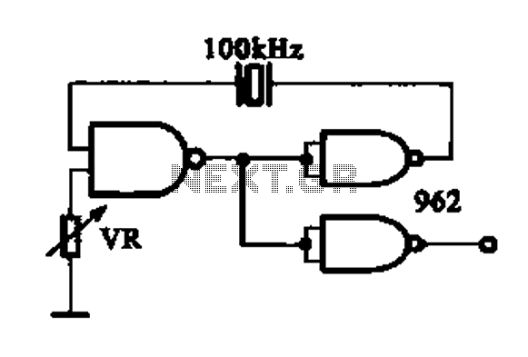
The DTL (Diode-Transistor Logic) integrated circuit is a fundamental component in digital electronics, characterized by its use of diodes and bipolar junction transistors to perform logical operations. The crystal oscillator serves as a critical element in this circuit, providing a stable frequency reference necessary for timing applications. The specified oscillation frequencies of 100 kHz and 1 MHz are typical for various digital applications, including clock generation and signal modulation.
The gate circuit, integral to the functioning of the DTL integrated circuit, is designed to control the flow of signals to the oscillator. It ensures that the oscillator operates correctly by providing the necessary input signals and maintaining the desired output characteristics. The interaction between the oscillator and the gate circuit is crucial for achieving stable and reliable oscillation, which is essential for the overall performance of the integrated circuit.
In practical applications, the DTL integrated circuit can be utilized in a range of devices, such as timers, frequency generators, and communication systems, where precise timing and frequency control are paramount. The design and layout of the circuit must consider factors such as power supply decoupling, signal integrity, and thermal management to ensure optimal operation within the specified frequency range.DTL integrated circuit constituted by a crystal oscillator a DTL is shown by the crystal oscillator integrated circuits, and the oscillation frequency is 100 kHz and 1 MHz. It is constituted by a gate circuit to provide a signal for the oscillator circuitry DTL.
Related Circuits
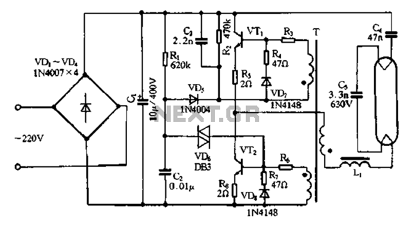
Bridge rectifier circuit in the electronic ballast application circuit The bridge rectifier circuit is a crucial component in electronic ballast applications, primarily utilized for converting alternating current (AC) to direct current (DC). This conversion is essential for powering various electronic...
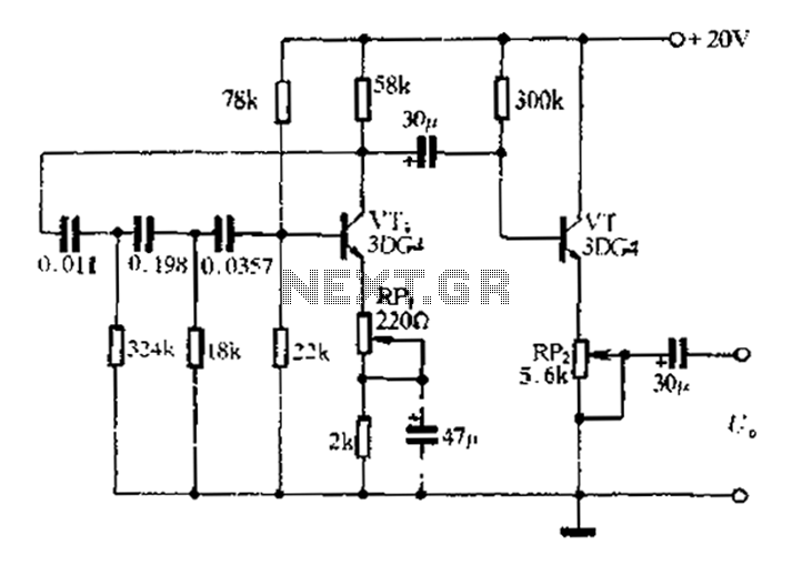
1 kHz RC phase shift oscillator circuit The 1 kHz RC phase shift oscillator circuit is designed to generate a continuous sine wave output at a frequency of 1 kHz. This circuit typically utilizes a combination of resistors and capacitors...
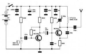
Simple FM Transmitter Circuit This simple FM transmitter circuit was built using a transistor with a transmission distance of about 300m around your home. The simple FM transmitter circuit utilizes a transistor to modulate audio signals onto a radio frequency...

Illuminate your tabletop with this stylish White LED Lamp. It is powered through a USB port, making it perfect for taking notes while browsing the internet. The USB port can provide a convenient power source. The White LED Lamp is...
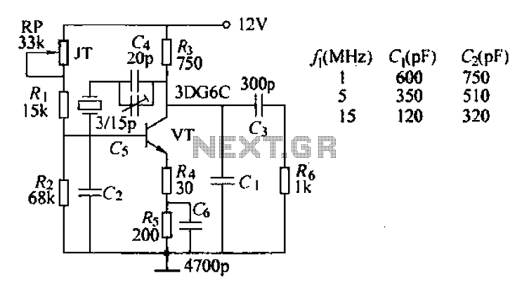
The typical crystal oscillator circuit depicted in the figure is a three-point oscillator designed for capacitance feedback. The oscillator's frequency is influenced by the series and parallel resonant frequencies of the crystal. This type of circuit is commonly known...
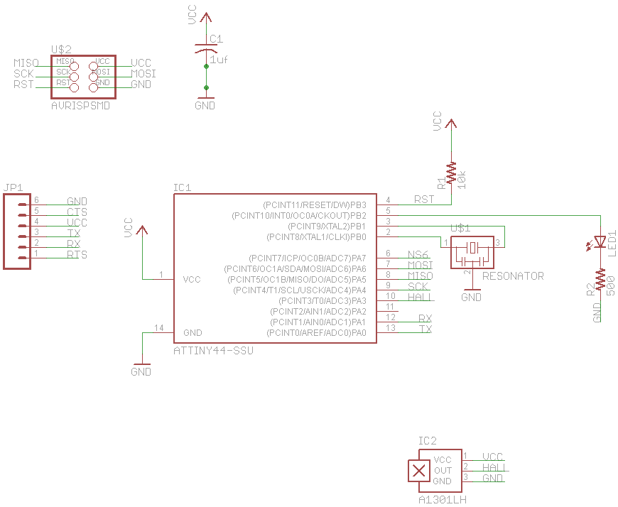
The final project involves cycling rollers that require a method to sense the rotational speed of one of the rollers. Speed sensors on bicycles typically function by detecting a magnet attached to a spoke on one of the wheels...