
DTMF decoder with voice!

The Talking Phone Dial Monitor circuit is designed to enhance the usability of touch-tone telephones by audibly confirming the numbers dialed. The core of the system includes an electret microphone for audio input, which is directly interfaced with an integrated circuit (IC) from Information Storage Devices. This IC is responsible for converting the spoken numbers into analog data that can be stored in memory cells.
The schematic incorporates several critical components for functionality. The telephone line interface is established through capacitor C1 and transformer T1. Capacitor C1, rated for 250 volts, ensures isolation from high voltages present in the telephone line, particularly during ringing. Transformer T1 further isolates the circuit while providing necessary voltage transformation.
A dual-tone multi-frequency (DTMF) decoder, designated as IC1 (MC145436A), interprets the audio tones generated by the telephone keypad. As numbers are dialed, IC1 outputs binary data corresponding to the dialed numbers. This data is then routed to a FIFO memory circuit, IC2 (IDT72401L10P), which temporarily stores the binary information. The data valid (DV) signal from IC1 indicates when new data is available, allowing the FIFO to increment its address pointer for storage.
The output of the FIFO is connected to the address pins of the ISD1420 voice storage device, IC3. This connection is facilitated through 10K resistors, which help to protect the components and ensure proper signal levels. The IC3 is capable of storing multiple voice messages, with the storage addresses being selectable via a DIP switch (SA). This feature allows users to record and playback voice messages corresponding to different storage locations.
Additionally, a zener diode (D1) is employed on the secondary side of the transformer to protect the DTMF decoder from voltage spikes. The oscillator circuit, composed of resistor R1 and a 3.58 MHz crystal (XTAL), generates the clock signals necessary for the operation of the DTMF decoder.
Overall, this Talking Phone Dial Monitor circuit provides a practical solution for users who may have difficulty seeing the dial pad, enhancing accessibility through audio feedback.The Talking Phone Dial Monitor detects the tones generated when numbers are dialed on your touch tone telephone and speaks the numbers that were dialed. This verifies that you dialed the correct number and is especially useful when the keypad is not well lighted or if the person dialing cannot see the keypad well for any reason.
The numbers that are spoken can be prerecorded by speaking into a built-in microphone and can be re-recorded at any time if desired. This design makes use of an integrated circuit made by Information Storage Devices that stores spoken words in memory cells as analog data. Voice can be stored by speaking into an electret microphone connected directly to the IC. It also has a built-in audio amplifier that directly drives a speaker. Figure 1 is a schematic of the talking monitor. The telephone line is connected to the circuits through capacitor C1 and transformer T1 which isolate the line from the circuits.
A dual tone multi frequency (DTMF) decoder IC1 decodes the tones generated by your telephone when a number is dialed. The decoded tones appear at the output pins of IC1 as binary information which is fed into a first in, first out (FIFO) memory circuit IC2.
Capacitor C1 must have a voltage rating of 250 volts to withstand the high voltage produced by a ring signal. On the secondary side of T1, zener diode D1 clamps any high voltage spikes in both the positive and negative direction that might otherwise damage MC145436A touch tone decoder IC1.
Resistor R1 and 3.58 Mhz crystal XTAL together with an on-chip oscillator generate clock pulses necessary to the operation of IC1. Data valid (DV) pin 12 goes high when tones are decoded and valid binary data appears at output pins 2, 1, 14 and 13.
DV connects to shift in (SI) pin 3 of the IDT72401L10P FIFO IC2 and increments its address pointer when new data is ready to be stored. Output pins 13, 12, 11 and 10 connect through 10K resistors to the address input pins of ISD1420 voice message storage device IC3.
These address pins can also be manually selected by DIP switch SA to record voice at any of the twelve available storage locations. All DIP switch positions, 1, 2, 3 and 4 must remain open during playback operation of the monitor. 🔗 External reference
Related Circuits
It is possible to implement a circuit using both P-MOS and N-MOS transistors, referred to as CMOS technology. In this context, a three-terminal NAND gate can be constructed. This gate is classified as a universal gate, widely utilized in...
The circuit uses a NTE1690 DTMF dialer chip and a PIC16F690 microcontroller. Because this is an IP phone and I cannot just send the DTMF tones over the line, the easiest place to plug in the box is between...
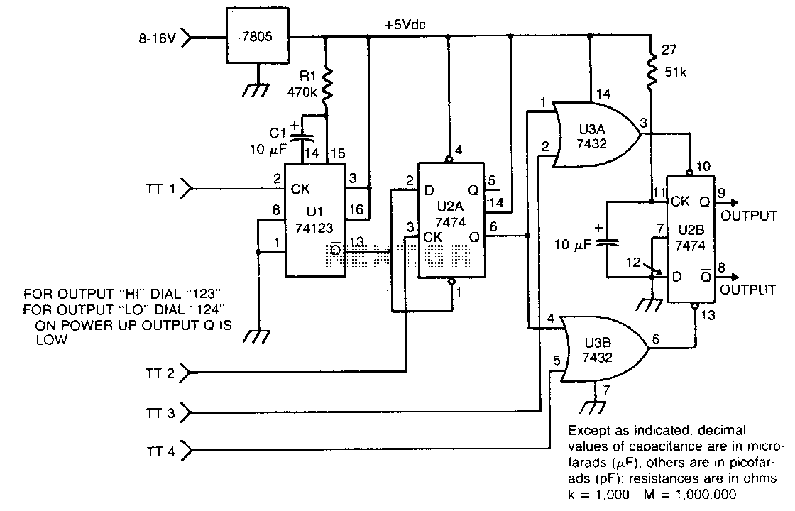
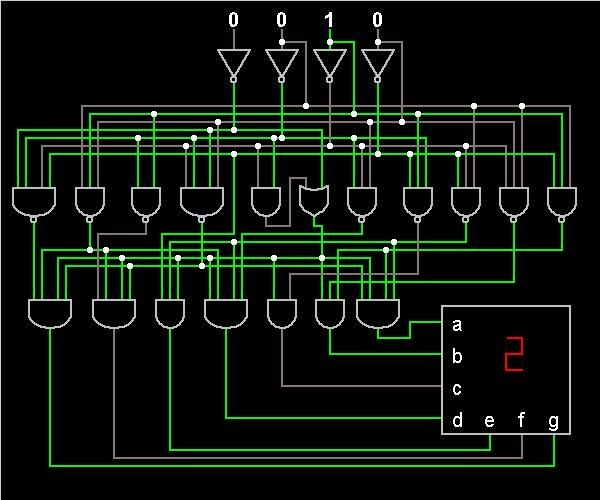
The circuit takes active low inputs from a Touch Tone decoder and reacts to a proper sequence of digits. The proper sequence is determined by which Touch Tone digits the user connects to the sequence decoder inputs TT1, TT2,...
To simplify the driver circuit, a multiplexer circuit can be utilized as a solution. With this multiplexed BCD decoder, only one BCD is required. A multiplexer (MUX) is an essential component in digital circuits, allowing multiple input signals to be...
Surround Sound Decoder circuit diagram. The circuit's operation begins when the stereo sound signal carries surround sound information through the master volume section. This drives the Left channel (Lch), which is connected to Model TL072 IC1A and IC1B, with...
DTMF (Dual Tone Multi-Frequency) signaling is commonly used in telephone networks, including home phones, cellular phones, and SPC exchanges, for transmitting and receiving numbers. DTMF technology is also applicable in scenarios such as power line carrier communication. It is...