
Multiplexed BCD Decoder 7 Segments Driver
A multiplexer (MUX) is an essential component in digital circuits, allowing multiple input signals to be routed to a single output line. In the context of a BCD (Binary-Coded Decimal) decoder, the use of a multiplexer can significantly reduce the complexity of the driver circuit. The BCD decoder converts binary inputs into a decimal output, which is useful in applications requiring numerical displays or control systems.
In this design, a single BCD decoder can be employed in conjunction with the multiplexer to manage multiple BCD inputs efficiently. The multiplexer selects one of the several BCD inputs based on control signals, enabling the decoder to process only the active input at any given time. This configuration not only minimizes the number of components needed but also streamlines the overall circuit design.
The implementation involves connecting the outputs of the multiplexer to the input of the BCD decoder. Control lines determine which BCD input is active, allowing for dynamic selection of the input data. The output of the BCD decoder can then drive a display or other downstream components.
The benefits of this approach include reduced power consumption, lower component count, and simplified wiring, which can lead to enhanced reliability and ease of troubleshooting. Additionally, this configuration can be adapted to various applications, such as digital displays, counters, or any system requiring the conversion of binary data into a decimal format.
In summary, integrating a multiplexer with a BCD decoder provides an efficient solution for managing multiple binary inputs, thereby simplifying the design and operation of digital circuits.To save the complexity of driver circuit, a multiplexer icrcuit can be used for the solution. With this multiplexed BCD decoder, we can use only one BCD.. 🔗 External reference
Related Circuits
Balanced signals consist of two lines that have opposite phases and should be received with a differential input receiver. Balanced signals are employed in many applications. Balanced signals are primarily used in audio and communication systems to minimize noise and interference....
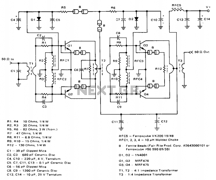
The amplifier achieves a total power gain of approximately 25 dB, utilizing a construction technique that incorporates low-cost components throughout. The MRF476 is rated as a 3-watt device, while the MRF475 delivers an output power of 12 watts. Both...
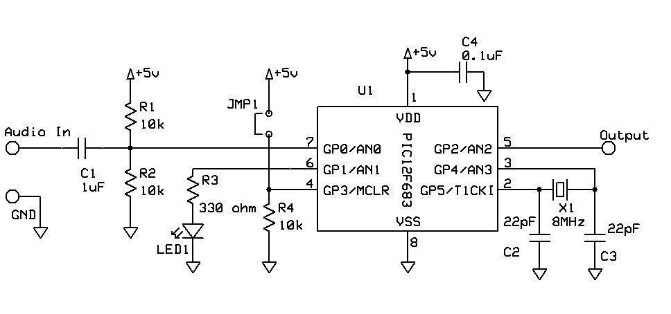
DTMF Touch Tone Decoder Using Microchip PIC Microprocessor. This project contains the details of using a Microchip PIC12F683 8-bit microprocessor to detect Dual-Tone Multi-Frequency (DTMF) signals. The DTMF Touch Tone Decoder circuit utilizes the Microchip PIC12F683 microprocessor, which is an...
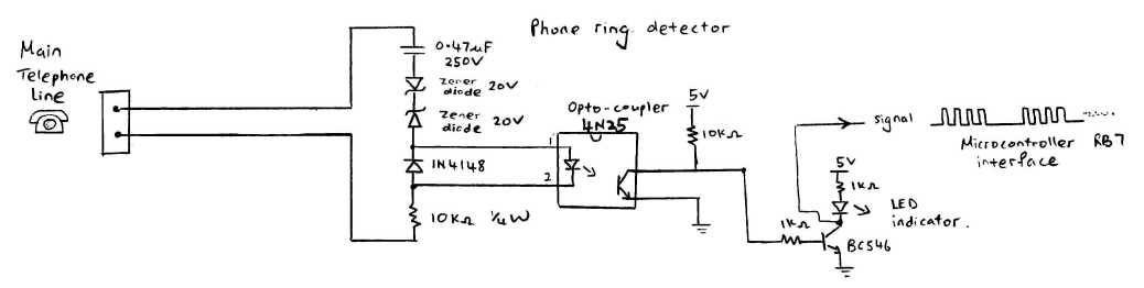
This circuit detects the dial tone from a telephone line and decodes the keypad pressed on the remote telephone. The dial tone heard when picking up the phone is referred to as Dual Tone Multi-Frequency (DTMF). This name originates...
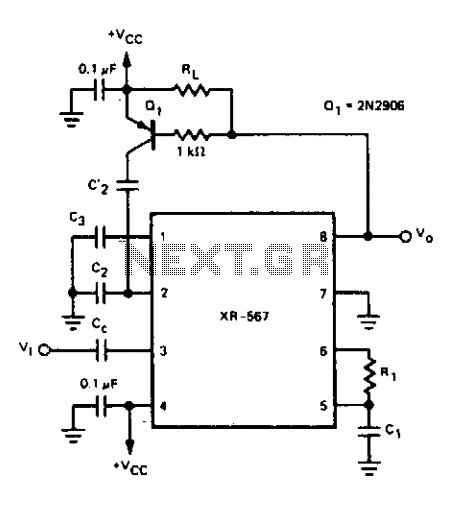
For certain applications, it is crucial to utilize a tone decoder that features a narrow bandwidth and a fast response time. This objective can be achieved with the dual time constant tone decoder circuit presented. The circuit incorporates two...

This device offers numerous implementation possibilities due to its wide input voltage range and large maximum output current across a broad output voltage spectrum. It features long battery life and low power consumption owing to its high efficiency and...
Warning: include(partials/cookie-banner.php): Failed to open stream: Permission denied in /var/www/html/nextgr/view-circuit.php on line 713
Warning: include(): Failed opening 'partials/cookie-banner.php' for inclusion (include_path='.:/usr/share/php') in /var/www/html/nextgr/view-circuit.php on line 713