
Tone dial sequence decoder
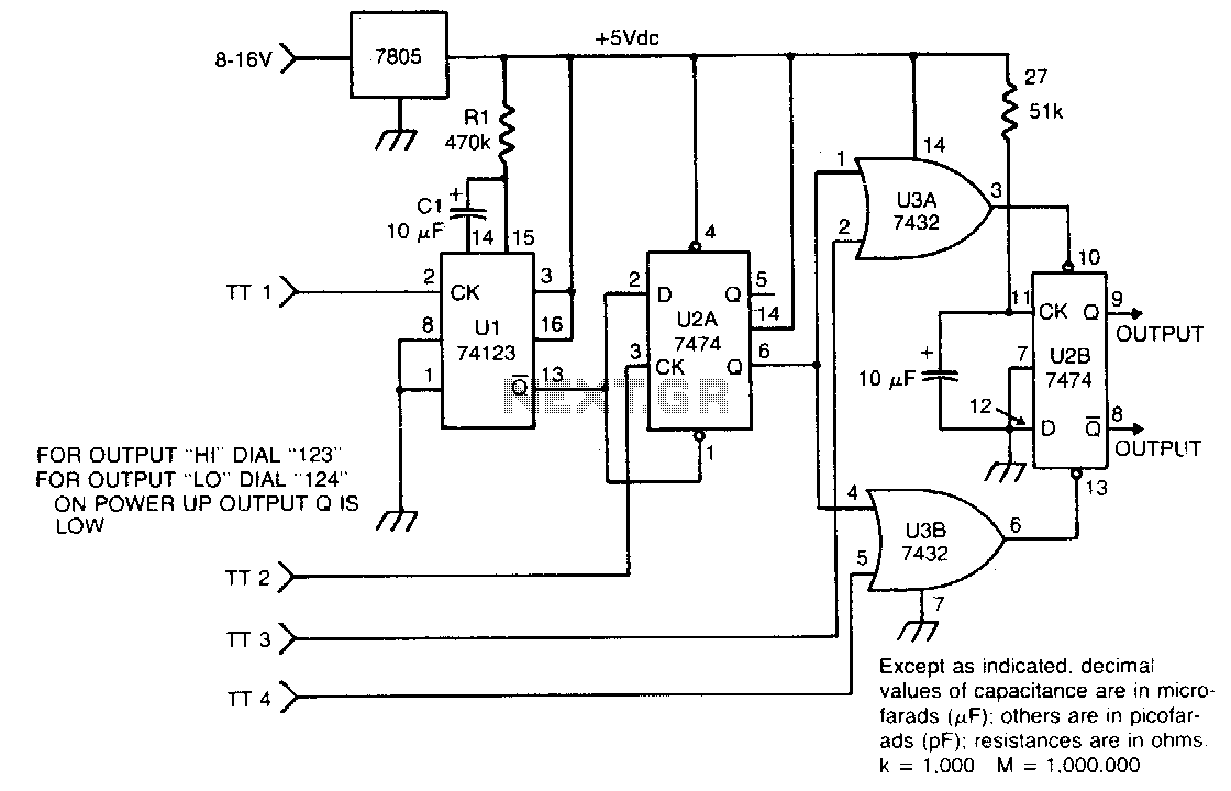
The circuit is designed to interface with a Touch Tone decoder that operates with active low logic levels. The primary function of the circuit is to detect a specific sequence of digits inputted through the decoder. The decoder has four input channels, labeled TT1, TT2, TT3, and TT4, which correspond to the Touch Tone digits that can be connected by the user.
When a digit is pressed on a Touch Tone keypad, the corresponding output from the decoder goes low, indicating a valid input. The circuit monitors these inputs and requires a predefined sequence to be activated. For instance, if the user connects the digits 1, 2, 3, and 4 to TT1, TT2, TT3, and TT4 respectively, the circuit will only respond when these inputs are received in the correct order.
The circuit may utilize a microcontroller or a combinational logic circuit to process the inputs. A simple microcontroller can be programmed to recognize the sequence and execute a specific action, such as lighting an LED, activating a relay, or sending a signal to another system. In more complex designs, additional components such as debounce circuits may be included to ensure reliable detection of the Touch Tone inputs, preventing false triggering due to noise or mechanical bouncing of the keypad.
This circuit can be applied in various applications, including security systems, remote control devices, and automated systems where user input is necessary to trigger specific functions. Proper attention to the design of the input circuitry and the logic processing will ensure that the system operates correctly and reliably under different conditions.The circuit takes active low inputs from a Touch Tone decoder and reacts to a proper sequence of digits The proper sequence is determined by which Touch Tone digits the user connects to the sequence decoder inputs TT1, TT2, TT3, and TT4. 🔗 External reference
Related Circuits

Various types of paper were tested, including photo paper, telephone book paper, color magazine pages, dextrin-coated paper, and catalogs from electronic supply companies. Different temperatures of a hot iron and varying pressure levels were also experimented with. Several board...
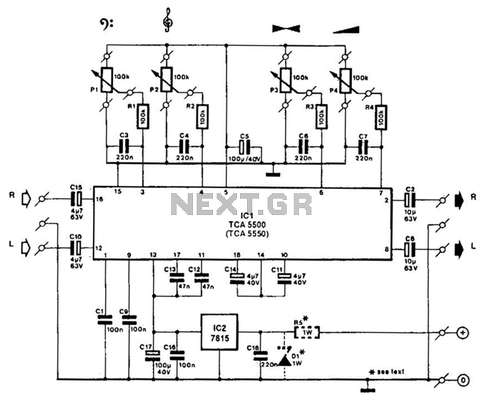
A Motorola TCA5500 or TCA5550 can be utilized to create a stereo preamplifier system equipped with tone controls. This circuit is designed to offer a gain of approximately 10 times, a tone-control range of 14 dB, and a volume...

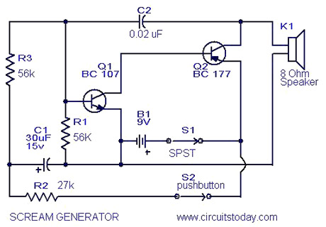
The circuit utilizes two unijunction transistors. The low-frequency sawtooth generated by Q1 modulates the high-frequency tone produced by Q2. The output is designed to feed into a high-impedance amplifier. Both Q1 and Q2 are 2N4871 transistors. The circuit comprises two...
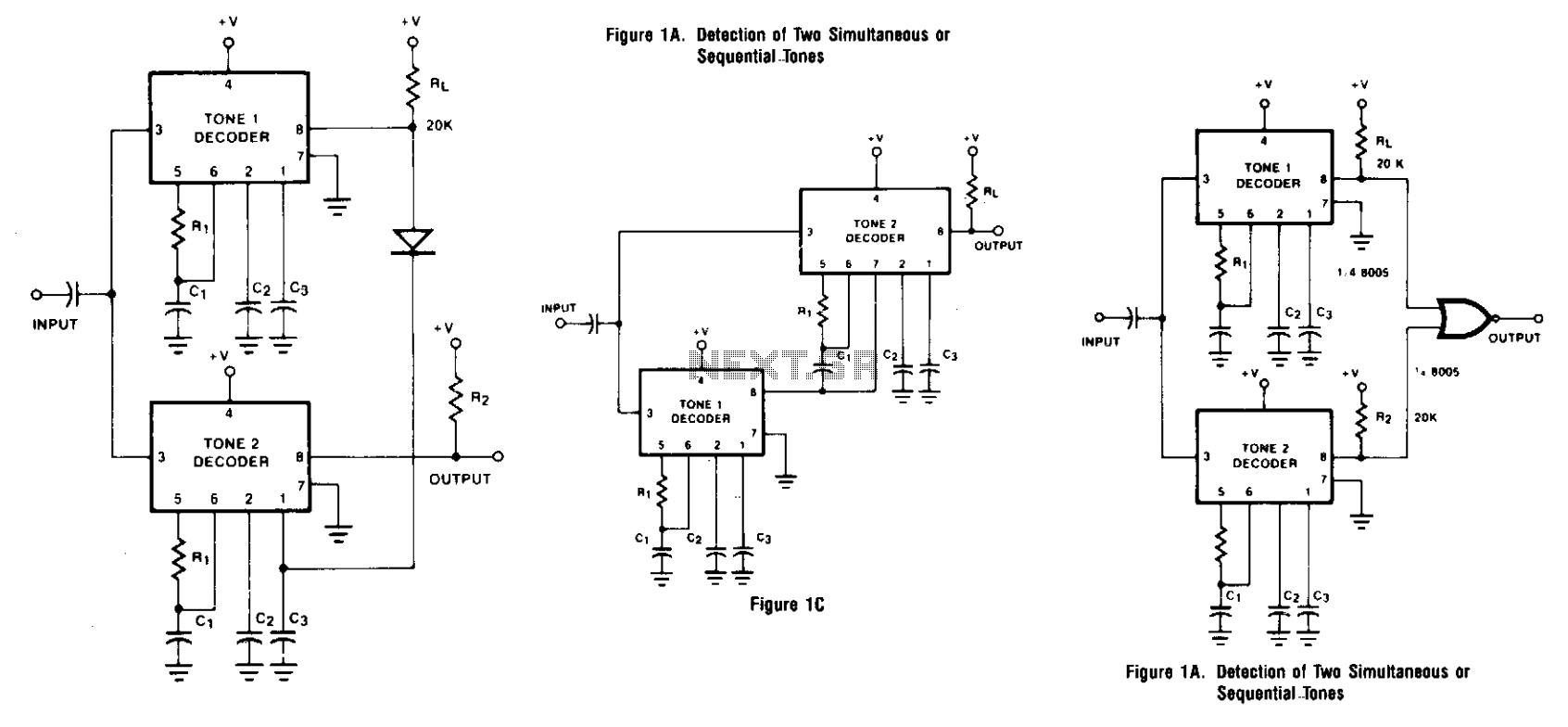
Two integrated tone decoders, XR-567 units, can be connected to allow for the decoding of simultaneous or sequential tones. Both units must be activated before an output is produced. Resistors R1 and R'1, along with capacitors C1 and C'1,...
Multi Tone Alarm Description This is a simple and easy-to-build multi-tone alarm circuit that can be used in burglar alarms or sirens. The circuit is based on the dual op-amp MC1458 and LM380. The two op-amps inside the MC1458...
This is a basic 555 squarewave oscillator used to produce a 1 kHz tone from an 8-ohm speaker. In the circuit on the left, the speaker is isolated from the oscillator by the NPN medium power transistor, which also...