
DTMF Proximity Detector
The DTMF-based IR proximity detector circuit is a sophisticated system that combines telecommunication technology with infrared sensing. The primary components include the DTMF generator and decoder, which work in tandem to produce and recognize specific audio frequencies. The DTMF generator (IC1) continuously outputs a tone corresponding to the digit '1', which is modulated onto the IR light emitted by IR LED1. This modulation is crucial as it allows the photodetector (D1) to differentiate between ambient IR light and the signal generated by the transmitter.
The use of a Darlington pair (T3 and T4) for amplifying the tone output enhances the IR LED's ability to project the modulated signal over a greater distance, ensuring reliable detection of nearby objects. The variable resistor (VR1) provides flexibility in adjusting the intensity of the IR light, which is essential for optimizing the detection range based on environmental conditions.
The design also emphasizes the importance of shielding the photodetector from direct IR light to prevent false positives, which could occur if the photodetector receives direct light from the IR LED instead of reflected light. This careful consideration in the layout ensures that the system operates effectively in various scenarios.
The output from the DTMF decoder (IC2) indicates the successful detection of an object by providing a high signal at the StD pin, which can be integrated into larger systems for further processing or triggering actions, such as activating alarms or counting objects. This versatility makes the DTMF-based IR proximity detector a valuable tool in security and automation applications.A DTMF-based IR transmitter and receiver pair can be used to realize a proximity detector. The circuit presented here enables you to detect any object capable of reflecting the IR beam and moving in front of the IR LED photo-detector pair up to a distance of about 12 cm from it. The circuit uses the commonly available telephony ICs such as dial-to ne generator 91214B/91215B (IC1) and DTMF decoder CM8870 (IC2) in conjunction with infrared LED (IR LED1), photodiode D1, and other components as shown in the figure. A properly regulated 5V DC power supply is required for operation of the circuit. The transmitter part is configured around dialer IC1. Its row 1 (pin 15) and column 1 (pin 12) get connected together via transistor T2 after a power-on delay (determined by capacitor C1 and resistors R1 and R16 in the base circuit of the transistor) to generate DTMF tone (combination of 697 Hz and 1209 Hz) corresponding to keypad digit 1 continuously.
LED 2 is used to indicate the tone output from IC3. This tone output is amplified by Darlington transistor pair of T3 and T4 to drive IR LED1 via variable resistor VR1 in series with fixed 10-ohm resistor R14. Thus IR LED1 produces tone-modulated IR light. Variable resistor VR1 controls the emission level to vary the transmission range. LED 3 indicates that transmission is taking place. A part of modulated IR light signal transmitted by IR LED1, after reflection from an object, falls on photodetector diode D1.
(The photodetector is to be shielded from direct IR light transmission path of IR LED1 by using any opaque partition so that it receives only the reflected IR light. ) On detection of the signal by photodetector, it is coupled to DTMF decoder IC2 through emitter-follower transistor T1.
When the valid tone pair is detected by the decoder, its StD pin 15 (shorted to TOE pin 10) goes high`. The detection of the object in proximity of IR transmitter-receiver combination is indicated by LED1.
The active-high logic output pulse (terminated at connector CON1, in the figure) can be used to switch on/off any device (such as a siren via a latch and relay driver) or it can be used to clock a counter, etc. This DTMF proximity detector finds applications in burglar alarms, object counter and tachometers, etc.
🔗 External reference
Related Circuits

The MC1596/MC1496 serves as an effective single sideband (SSB) product detector. This detector exhibits a sensitivity of 3 microvolts and a dynamic range of 90 dB while functioning at an intermediate frequency of 5 MHz. It is designed to...

The circuit diagram presented below illustrates a portable gas detector. This device primarily utilizes electrochemical sensors and features dual-channel micro-power amplifiers, specifically the ADA4505-2. These amplifiers are configured in both a constant potential (U2-A) and a transconductance configuration (U2-B)....
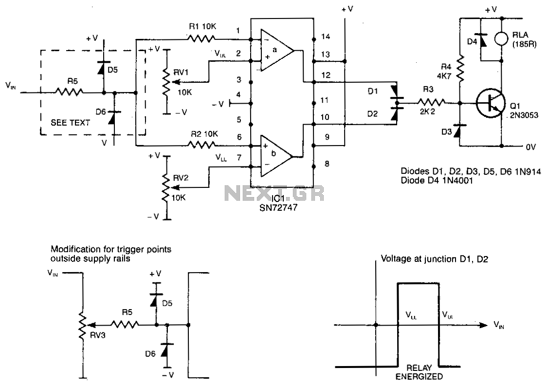
This circuit de-energizes a normally energized relay if the input voltage exceeds or falls below two individually set voltages. The transistor driving the relay is typically activated by resistor R4, keeping the relay energized. If the cathode of diodes...

A simple proximity detector can be created using this electronic circuit. This circuit responds to the presence of a conductive object within a specific range. The sensitivity of the circuit can be adjusted with potentiometer P1 to achieve the...

This circuit detects light and provides a voice warning. It responds to changes in light conditions, becoming active based on the position of switch S1. The circuit utilizes a light-dependent resistor (LDR) to sense ambient light levels. When the light...

VCR Camera Video Detector Switch Controller Circuit. This video detector switch controller circuit utilizes the video output from a VCR or camera to... This circuit functions as a video detector switch controller, designed to manage the video output from a...