
Proximity detector electronic project circuit design
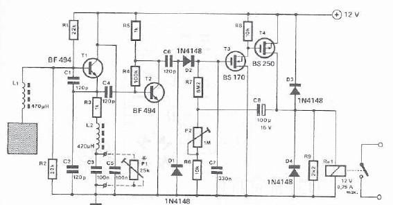
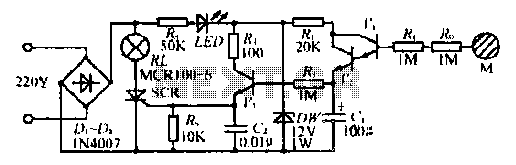
The proximity detector circuit operates on the principle of capacitance variation caused by the presence of conductive objects. The monostable oscillator, formed by transistor T1, generates a high-frequency signal, which is influenced by the capacitance of nearby conductive objects. The capacitors C1 and C2 are selected to ensure stable oscillation frequencies, typically around 1 MHz, allowing for reliable detection.
When a conductive object enters the detection field, it alters the effective capacitance seen by the oscillator, leading to a change in frequency. This change is detected and amplified, resulting in a high-frequency signal that is subsequently rectified. The rectified signal serves as a control pulse for the tipping stage, which is composed of transistors T3 and T4. This stage is responsible for activating the relay, which can control external devices or systems based on the proximity detection.
The use of VFETs (Vertical Field Effect Transistors) in the tipping stage allows for efficient control of the relay. VFETs provide advantages such as high efficiency and fast switching times, making them suitable for applications requiring rapid response. The switching time can be fine-tuned using potentiometer P2, allowing the user to adjust the response time of the relay activation based on specific application requirements.
Overall, this proximity detector circuit provides a straightforward and effective solution for detecting the presence of conductive objects, with adjustable sensitivity and reliable performance. It is applicable in various fields, including automation, security systems, and industrial applications, where non-contact detection is essential.A very simple proximity detector can be made using this electronic scheme. This electronic circuit reacts to the presence of a conductive object within a particular field. Circuit sensitivity can be adjusted with potentiometer P1 for the desired distance. The electronic circuit consists essentially of a monostable oscillator and a tipping stage. O scillator is built with transistor T1. This is why a flap that oscillator frequency is particularly stable, because the capacity of the transistor is in parallel with relatively large capacities C1 and C2 of the oscillating circuit. Surface acts as a sensor oscillator circuit capacity of, capacity may be small in comparison with C1 and C2.
in this configuration, the oscillator operates at about 1 MHz. High frequency signal is amplified and eventually rectified. In this way receives a control pulse to monostable tipping stage consisting of T3 and T4. By using VFET`s possible to order the relay switching by tipping stage. Switching time is determined by adjusting potentiometer P2. 🔗 External reference
Related Circuits
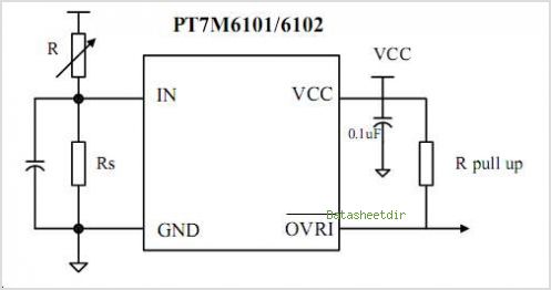
The PTB78560x is a series of 30 W rated isolated DC/DC converters designed to operate from a standard 24 V or 48 V telecom central office (CO) supply. Housed in a 12 package, each model features a wide adjustable...
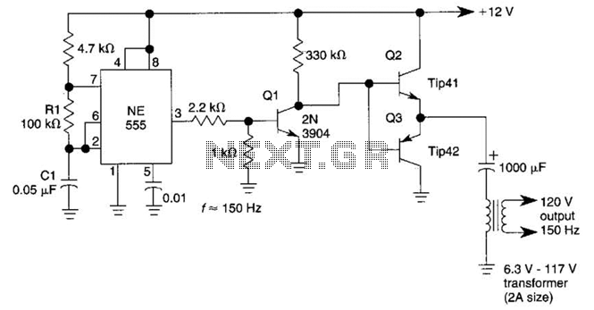
This DC-to-AC inverter utilizes the well-known 555 timer IC. A 555 oscillator circuit drives a buffer amplifier composed of transistors Q1, Q2, and Q3. The circuit operates at a frequency range of 150 to 160 Hz. Transformer T1 can...
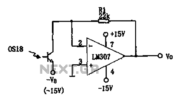
The circuit described is a photoelectric receiver amplifier designed to amplify the electrical signals generated by photodiodes or phototransistors in optoelectronic devices. When the intensity of incident light varies, the photosensitive device generates a corresponding voltage or current. The...
To comprehend the interconnections between the following circuits, it is essential to first review the concept chapter. It is at the discretion of the user to select one or two of these circuits for personal development. The discussion begins...
The circuit operates without a base current for the transistor. It turns off when the metal sheet is touched, causing the capacitor to start charging. The capacitor charges to 2V over a specified time. The circuit generates a conduction...
The circuit was taken from an old Elektor electronics magazine and is a compact design suitable for generating high-intensity lighting effects during festivals, parties, and gatherings. Diodes D1 and D2, along with capacitors C1 and C2, form a voltage...