
Stepper Motor controller with HC11
The circuit utilizes a 68HC11 microcontroller for implementing a PID control system, specifically designed for stepper motor control and encoder interfacing. The 68HC11 is programmed to read input from an encoder connected to PORTA pins PA0 and PA1, which allows for high-precision RPM measurements. The system is configured to operate in bootstrap mode, which facilitates the loading of the program into the microcontroller from an external source, such as a Loggyboard.
The provided assembly code snippet outlines the initialization and operational routines of the microcontroller. Key components of the circuit include:
1. **Memory Mapping**: The encoder interface and necessary registers are mapped to specific memory addresses. For instance, PORTA is assigned to $1000, PORTD to $1008, and various control registers such as SPCR, BAUD, and SCSR are mapped to subsequent addresses.
2. **Initialization**: The stack pointer is initialized, and the RS232 interface is set up for serial communication. The encoder count is initialized to zero, and an error flag is cleared to ensure a clean start.
3. **Main Loop**: The main loop of the program consists of a real-time interrupt routine that executes every 0.5 milliseconds. During each iteration, the encoder is read, and the current state of the encoder is compared with the last recorded state to determine the direction of rotation (increment or decrement).
4. **Encoder Handling**: The encoder reading routine isolates the relevant bits from PORTA to determine the state of the encoder. If the current state differs from the last recorded state, the encoder count is adjusted accordingly. This adjustment is crucial for accurately tracking the motor's position and speed.
5. **Error Handling**: The code includes error detection mechanisms that set an error flag if an unexpected encoder state is encountered. This ensures robust operation by preventing incorrect readings from affecting the control algorithm.
6. **Masking Logic**: The masking logic is implemented to ensure that only valid state transitions are considered. The expected values are masked to prevent erroneous increments or decrements, thereby enhancing the reliability of the encoder readings.
Overall, this circuit design showcases an effective integration of a microcontroller with an encoder for precise motor control applications, leveraging the capabilities of the 68HC11 for both processing and communication tasks.PID-Control with 68HC11. STEPPER CONTROL. 68HC11 read encoder. High accuracy RPM-measurement with 68HC11 The encoder is connected to PORTA PA0 and PA1 The board must be in BOOTSTRAB MODE (tested with Loggyboard) ********** listing from encoder.ass ************** $ZEROPAGE.INC PORTA EQU $1000 PORTD EQU $1008 DDRD EQU $1009 TOC3 EQU $101A TFLG1 EQU $1023 SPCR EQU $1028 BAUD EQU $102B SCCR1 EQU $102C SCCR2 EQU $102D SCSR EQU $102E SCDR EQU $102F BIT5 EQU 00100000B BIT6 EQU 01000000B ORG $B600 LDS #200 Load Stackpointer JSR RS_INIT RS232 INIT LDD #0 STD ENC_COUNT set to zero clr ERRORFLAG JSR SET__MASK init MASK ENC_PLUS and ENC_MINUS *********************************************************************** LOOP JSR REALTIME loop time 0,5 msec JSR ENCODER * ------------------ LDX PTR_SERIAL JSR X * ------------------ jmp LOOP *------------------------------------------ REALTIME LDAA #BIT5 wait for Real Time Interrupt WAIT_REAL2 BITA TFLG1 BEQ WAIT_REAL2 STAA TFLG1 * ---------------------- SetToc3 LDD TOC3 ADDD #1000 0,5 msec STD TOC3 * -------------------- RTS *************************************************** SET__MASK LDAA PORTA ANDA #00000011B STAA ENC_LAST bra SET_MASK2 ******************************************** ENCODER LDX ENC_COUNT LDAA PORTA ANDA #00000011B isolate input bits CMPA ENC_LAST BEQ ENCODER_EXIT if equal then exit STAA ENC_LAST save value for next cycle CMPA ENC_PLUS Increment or decrement ? BEQ ENCODERPLUS CMPA ENC_MINUS BEQ ENCODERMINUS LDAA #1 if error STAA ERRORFLAG ENCODER_EXIT RTS ENCODERMINUS DEX BRA SAVE_ENC_COUNT ENCODERPLUS INX SAVE_ENC_COUNT STX ENC_COUNT SET_MASK2 LDAA ENC_LAST The mask are only the next expected value BEQ MASK_01 CMPA #00000011B BEQ MASK_01 MASK_10 EORA #00000010B STAA ENC_PLUS LDAA ENC_LAST EORA #00000001B STAA ENC_MINUS RTS MASK_01 EORA #00000001B STAA ENC_PLUS LDAA ENC_LAST EORA #00000010B STAA ENC_MINUS RTS ***************************************************** $SERIAL.INC
🔗 External reference
Related Circuits
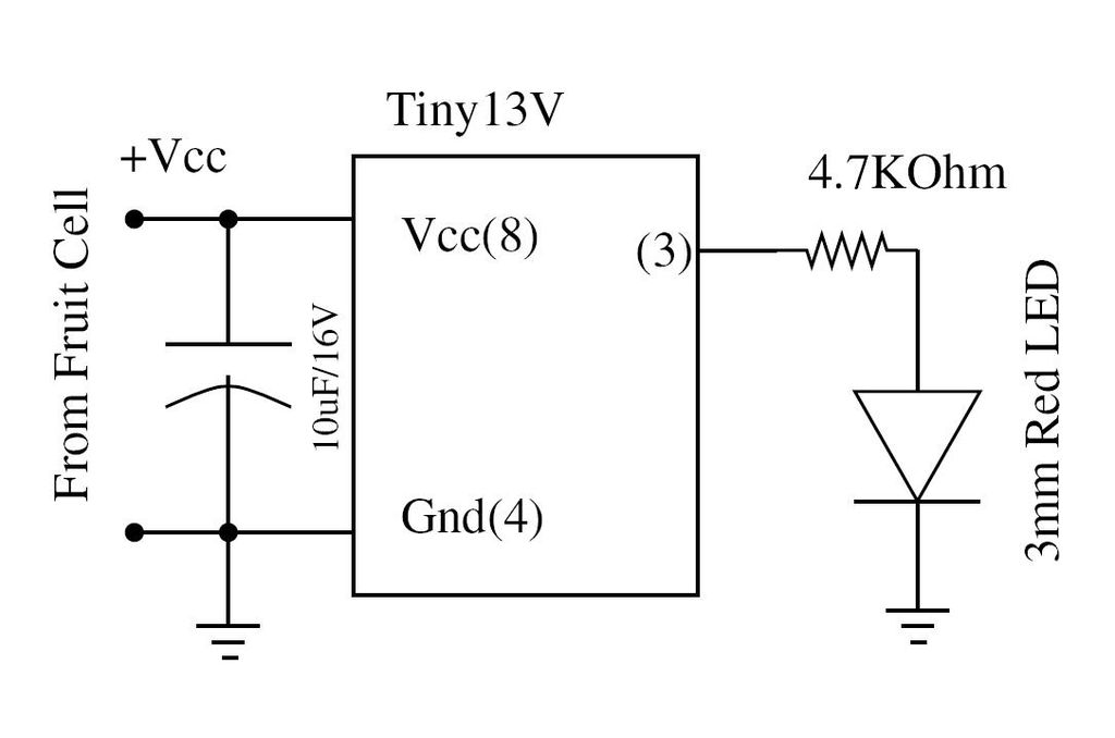
Wire the circuit diagram shown here on a breadboard. The choice of V type of AVR is important. For example, Tiny13V is very appropriate for such an application. To successfully implement the circuit diagram on a breadboard, several considerations must...
This simple microcontroller circuit regulates a servo motor based on a 3-state switch. The servo motor functions as an actuator with three positions. It consists of three wires: one for VCC, one for ground, and a third for position...
Below is a block diagram of modern automated systems that incorporate closed-loop feedback for motion control. They typically include a servo system that consists of various components. Automated systems utilizing closed-loop feedback mechanisms are designed to enhance precision and responsiveness...
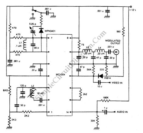
How can a television modulator be small and simple? First, it utilizes integrated circuits, and second, a TV modulator is essentially an amplitude modulator. Television modulators are essential components in the transmission of television signals, converting audio and video signals...
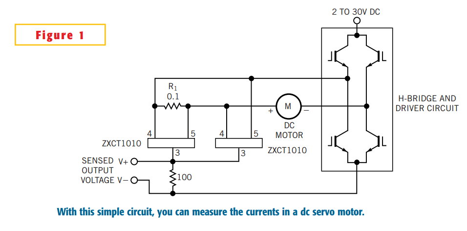
The simple circuit design in Figure 1 lets you measure all components of a current flowing in a dc servo motor. The rectified output of the circuit uses ground as a reference, so you can measure the output by...
This Project is used to control a single phase Motor from any where in the world through the telephone. The circuit consists of a DTMF tone detector and a powerful 8 bit Microcontroller AT89S52. The Microcontroller senses the DTMF...