
teleplone circuit

The telephone remote control system is designed to enhance user interaction with telecommunication devices by enabling remote management of specific functions. The circuit typically consists of a microcontroller, which serves as the central processing unit, and various input/output interfaces that facilitate communication between the user’s phone and the controlled device.
The microcontroller is programmed to interpret signals received from the phone, which may be transmitted via SMS, DTMF tones, or through a dedicated app. The input module can include a GSM module for SMS communication or a tone decoder for DTMF signal processing. Upon receiving a command, the microcontroller executes the corresponding function, which may involve activating relays, controlling motors, or interfacing with other electronic components.
The circuit design may include a power supply module to ensure stable operation, along with protection circuits to safeguard against voltage spikes. Additionally, the layout should consider signal integrity, minimizing noise and interference to maintain reliable communication between the phone and the remote control system.
To facilitate user interaction, the system may be equipped with status indicators such as LEDs to provide visual feedback on the operation of various functions. The overall design aims to create a user-friendly interface that allows for seamless control over the desired functionalities, thereby improving the efficiency and convenience of telephone operations.Telephone remote control for some of the ideas is the time, now can let you own a phone to do remote control, this is the procedure and circuit. Automatically executed complex functions. Facilitate the development of a telephone. 🔗 External reference
Related Circuits

This circuit was designed by Lazar Pancic from Yugoslavia. A typical PC sound card includes a microphone input, speaker output, and occasionally line inputs and outputs. The microphone input is specifically tailored for dynamic microphones with an impedance range...
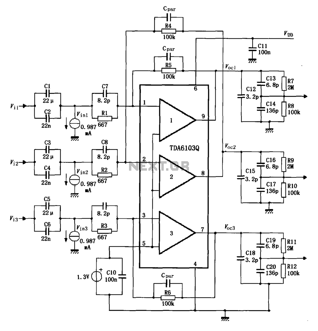
The TDA6103Q test circuit features a feedback factor of 1/150. Input signals Vi1, Vi2, and Vi3 are directed through an input resistor network that includes capacitors to the TDA6103Q pins 1, 2, and 3, which are part of the...
All electronic circuits were initially built on breadboards. Once the circuits were operational, they were soldered onto perfboards to create a more durable system. A power board was designed to stack two batteries in series, providing access to a...
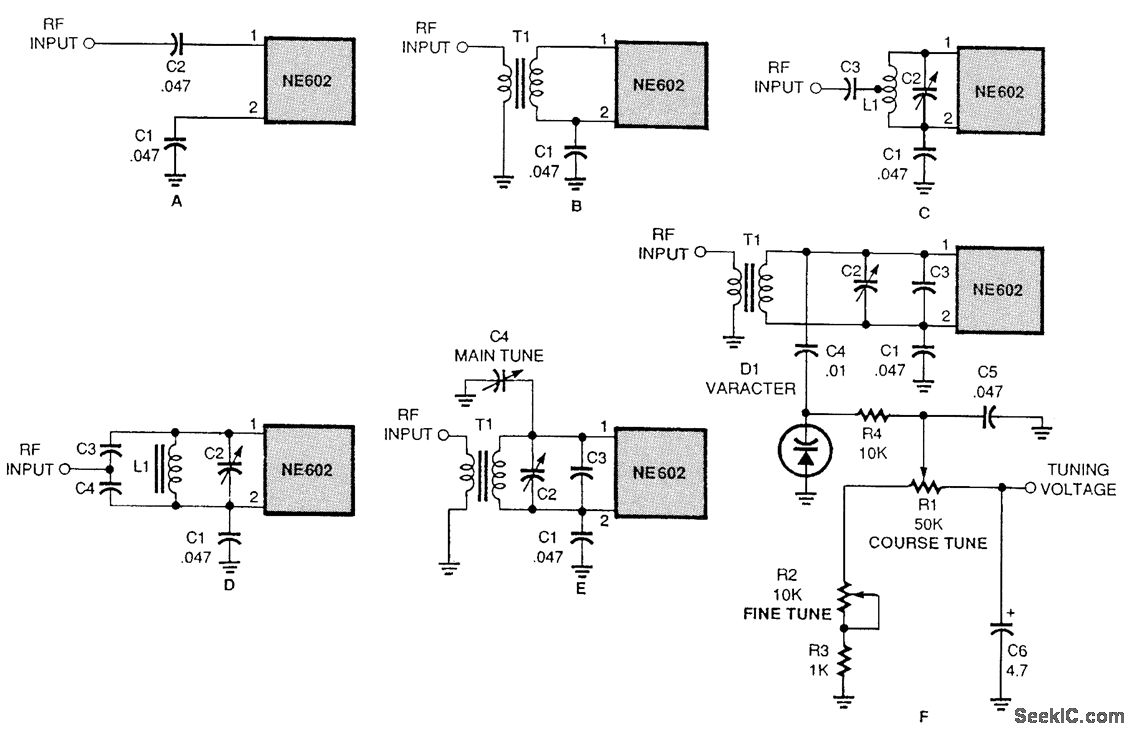
There are several methods to input a signal into the NE602. Simple untuned approaches (a and b) are viable. For tuning to a specific frequency, an LC resonant circuit with ungrounded trimmer capacitors (c and d) or grounded variable...
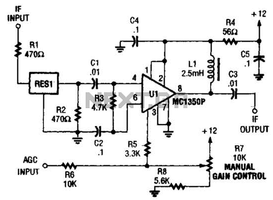
The ZN416E can be configured as a simple 455-kHz IF amplifier. In this case, the circuit's center and bandwidth are set by RES1 (a Murata CSB455E ceramic resonator). The ZN416E is a versatile integrated circuit designed for use as a...
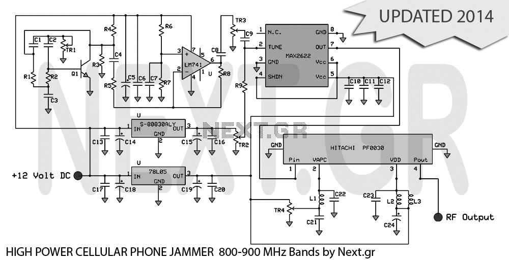
UPDATED 2014 This project presents the original high-power mobile phone jammer circuit, with all updates posted here. Caution is advised regarding the use of this device, as it is illegal. The purpose of sharing this circuit is solely for...