
Dual polarity power supply
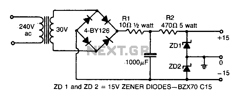
This circuit operates by utilizing a single transformer winding to supply alternating current (AC) to a full-wave bridge rectifier, which converts the AC voltage into direct current (DC). The bridge rectifier consists of four diodes arranged in a configuration that allows current to flow through the load during both halves of the AC cycle, thus providing a more stable output voltage.
The two zener diodes are employed to create a dual voltage output. By placing the zener diodes in series, each diode can be selected to have a specific breakdown voltage, allowing for precise voltage regulation. The center point between the two zener diodes serves as the ground reference for the circuit, effectively splitting the output into positive and negative voltages relative to this ground point.
In addition, the filter capacitor is essential for smoothing the rectified voltage. It stores charge and releases it when the rectified voltage drops, thus reducing ripple in the output. Care must be taken to ensure that the capacitor is not grounded through its case, as this could introduce noise and instability into the circuit. Instead, the capacitor should be connected to the appropriate points in the circuit to maintain the integrity of the voltage levels and ensure reliable performance.
This configuration is commonly used in various applications where dual power supplies are required, such as operational amplifiers, analog circuits, and signal processing systems. Proper selection of the transformer, zener diodes, and filter capacitor values is critical to achieving the desired output characteristics and ensuring the circuit operates within its intended specifications.This simple circuit gives a positive and negative supply from a single transformer winding and one full-wave bridge. Two zener diodes in series provide the voltage division and their centerpoint is grounded (The filter capacitor must not be grounded via its case). 🔗 External reference
Related Circuits
For the 60W amplifier, a nominal (full load) supply of +/- 35V is required, so a 25-0-25 secondary is ideal - however, see Updates, below. The circuit for the supply is shown below, and uses separate rectifiers, capacitors and...
Construct a low-cost and relatively simple robot that activates whenever a desk lamp is illuminated. The design does not incorporate any sensors. This robot can be designed using basic electronic components to create a simple activation mechanism based on light...
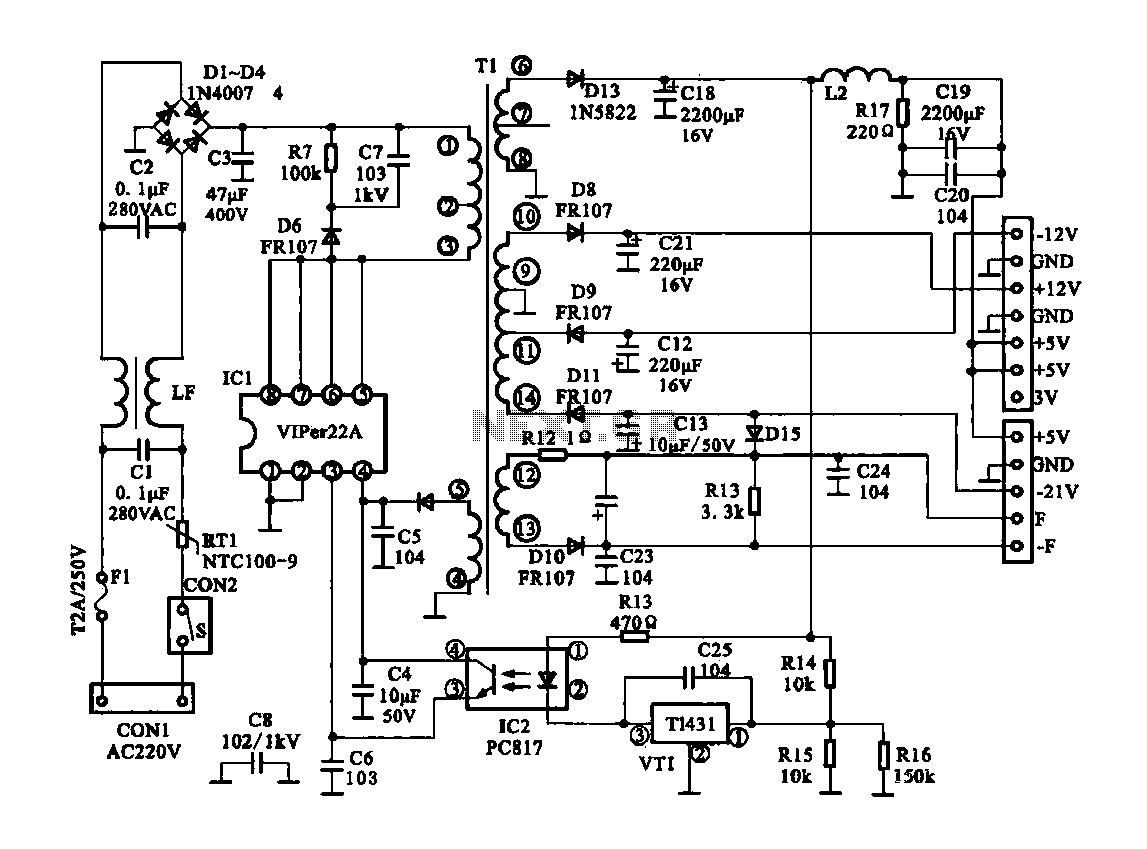
The Dragon ZL-2801A is a DVD machine that utilizes a switching power supply circuit. The circuit primarily consists of an AC input circuit, a rectifier filter wave circuit, an oscillation circuit switch, a switch transformer (Tl), a secondary rectifier,...
To obtain the power supply graphs on the previous page, the circuit is designed to independently monitor the power sources with the addition of a few resistors. Diode D3 allows the solar panel voltage to charge the batteries, while...
This is a simple circuit of a low-power voltage regulator reference. This circuit can produce a stable voltage reference. The low-power voltage regulator reference circuit is designed to provide a consistent output voltage, which is crucial for various electronic applications...
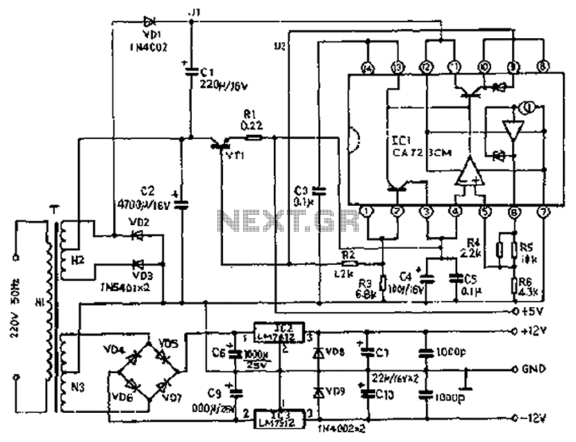
The circuit depicted features a secondary N3 center tap transformer (T) with a common point connecting diodes VD2 and VD3 to positive electrodes, along with capacitors C2, C6, C7, and negative electrodes connected to capacitors C9 and C10. Additional...