
dual power supply
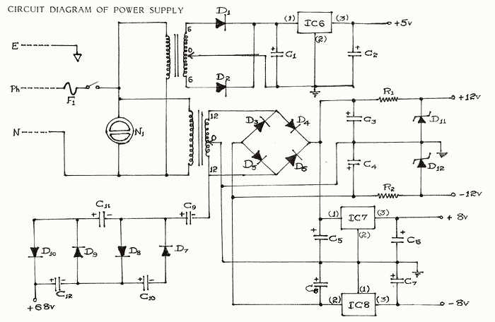
The design of the DC power supply circuit is essential for ensuring the reliable operation of electronic devices. The use of transformers allows for voltage stepping down from the high AC mains voltage to lower DC levels required by various components. The first transformer, with a 6-0-6V output, is crucial for supplying power to sensitive circuits such as the digital panel meter and temperature reference network. The full-wave rectifier converts the AC voltage to pulsating DC, which is then smoothed out by the capacitive filter, providing a more stable voltage output.
The three-terminal voltage regulator (IC6) plays a vital role in maintaining a consistent +5V output despite variations in input voltage or load conditions. This regulator is designed to handle a maximum input voltage of 35V, which provides a safety margin when considering potential fluctuations in the mains supply. The internal current limiting and thermal shutdown features of the regulator ensure that it operates safely and efficiently, reducing the risk of damage under fault conditions.
The second transformer, providing a 12-0-12V output, is utilized for powering other components in the circuit. The bridge rectifier, constructed from diodes, converts the AC output from the transformer into a usable DC voltage. The filtering stage following the rectification is equally important to ensure that the output voltage is stable and free from ripple, allowing the connected circuits to operate effectively.
Overall, the design considerations in this DC power supply circuit highlight the importance of safety, efficiency, and reliability in electronic applications. The choice of components and the configuration of the circuit are critical in achieving the desired performance and ensuring that the electronic devices function as intended.Every electronic gadget primarily needs a D. C, power supply to energize it. It also forms the basic requirement for any constructional project. consequently there is a need to obtain multiple voltage values for cost reduction, convenience and compact arrangement for all the above applications The required D. C. power supply is usually obtained by m eans of a transformer. It is also possible to have transformer less power supplies. Though the elimination of the transformer makes the circuit compact, economical and simple, also facilitating quick assembly and built in short circuit protection, certain drawbacks creep in. These power supplies are useful only for low current applications. Special safety precautions are to be followed while using them. Physical contact should be strictly avoided, since the output terminals are not isolated from A. C. mains supply. This obviously necessitates the use of a transformer. By suitable modification it is possible to obtain multiple/ fractional dual voltages from a transformer.
Different not-so obvious voltage values can also be obtained from the transformer by rectification circuits. The output so obtained from a transformer secondary is unregulated. For good load regulation, the internal impedance of any power supply should be as low as possible. The regulation can be improved either by resistor zener method or series regulator method. However, the three-terminal regulators greatly simplify the power regulation problem. These regulators need no external components. They employ internal current limiting and thermal shutdown which make them tough. For simplicity, compactness, convenience and accuracy the use of three terminal regulators is ideal.
These IC voltage regulators are freely available in various ranges both positive and negative. A functional schematic of a three terminal regulator is shown in the datasheet. It can be seen that the device is a complete regulator, with built-in reference, error amplifier, series pass transistor and protection circuits. The protection circuits include current limiting, safe area protection to limit dissipation in the series pass transistor and thermal shut down to limit temperature.
Low power IC voltage regulators of the 78L series used in our measuring instrument are now so cheap that they represent an economic alternative to simple zener-npn stabilisers. In addition they offer the advantages of better regulation, current limiting/short circuit protection at 1000 mA and thermal shunt down in the event of excessive power dissipation.
In fact, virtually the only way in which these regulators can be damaged is by incorrect polarity or by an excessive input voltage. Regulators in the 78L series upto the 8v type will withstand input voltages upto about 35v, whilst the 24v type will withstand 40v.
Normally, of course, the regulators would not be operated with such a large input-output differential as this would lead to excess power dissipation. All the regulators in the 78L series will deliver a maximum current of 1000mA provided the input- output voltage differential does not exceed 7v.
Otherwise excessive power dissipation will result, causing thermal Two transformers have been used to step down the voltage from 230-250v a. c. mains input. One of the transformers produces an output of 6-0-6v at the secondary terminals. This output is fed to a full wave rectifier and a capacitive filter. The filtered output is fed to IC6 which is a 3 pin voltage regulator which gives a regulated output of + 5v.
This is used to activate the DPM circuit. It is also fed to the temperature network as a precision voltage reference source. The other transformer produces an output of 12-0-12v at its secondary terminals. The centre tap is grounded like in the previous case. The other two terminals of the secondary are fed to a bridge rectifier constructed using diodes. The rectified output is filtered by using 🔗 External reference
Related Circuits
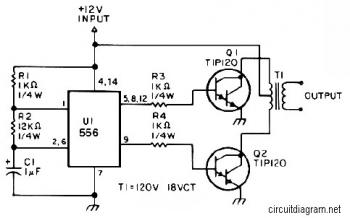
The first section of the 555 timer is configured as an astable oscillator, with resistors R2 and capacitor C1 determining the frequency. The output is available at pin 5. The second section is set up as a phase inverter,...
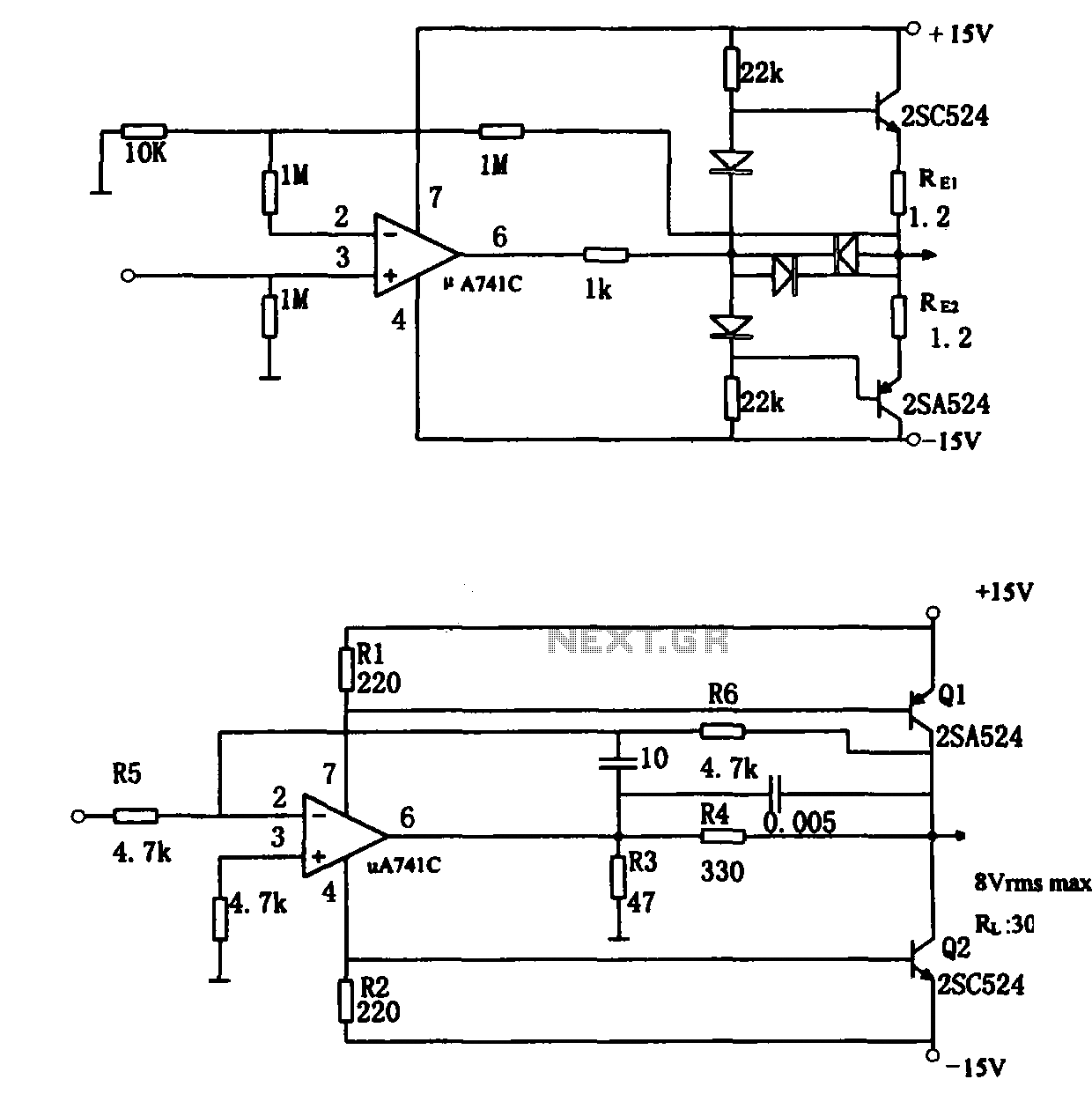
The direct coupling audio power amplifier utilizes an integrated operational amplifier. There are typically two practical configurations. The first configuration, depicted in (a), features a circuit structure that includes the output of the operational amplifier and a complementary symmetry...
This document describes how to construct a dual polarity linear power supply which can be configured for any positive or negative voltage between 1.2-35V. A power supply is the fundamental building block of all but the simplest of electronic...

This is a single-zone alarm system featuring independently adjustable Exit, Entry, and Siren Cut-Off timers. It is compatible with standard normally-closed input devices such as magnetic-reed contacts, foil tape, and passive infrared sensors (PIRs). A mains power supply can...
Under the loading condition of the resistance, the output voltage (Uo) variable range is from 30V to 36V, with a maximum output current (Imax) of 2A. When the input voltage (U2) changes from 15V to 21V, the voltage regulation...
The voltage requirement for the Solidus is significantly higher than what your circuit currently provides. The Solidus device operates at a voltage level that exceeds the specifications of the existing circuit. To accommodate this requirement, circuit modifications will need to...