
USB-Powered PIC Programmer
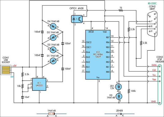
The circuit utilizes a 555 timer IC configured in astable mode to produce a square wave output that serves as the programming voltage for the PIC16F84 microcontroller. The frequency and duty cycle of the square wave can be adjusted by varying the resistors and capacitor connected to the timer. This programming voltage is essential for writing data to the flash memory of the microcontroller.
The circuit typically includes a power supply section that provides the necessary voltage levels for both the 555 timer and the PIC16F84. A resistor-capacitor (RC) network is used to set the timing characteristics of the 555 timer, which directly influences the programming pulse width and frequency. The output from the 555 timer is then routed to the programming pin of the PIC16F84, ensuring that the microcontroller receives the correct voltage levels during programming.
Additional components, such as diodes and transistors, may be included in the circuit to protect against voltage spikes and to control the flow of current to the microcontroller. Proper layout and grounding techniques should be employed to minimize noise and interference, which can adversely affect the programming process.
This circuit design is particularly useful for hobbyists and engineers working with PIC microcontrollers, as it provides a cost-effective and straightforward solution for programming flash memory devices. Careful attention to component selection and circuit configuration will enhance the reliability and performance of the programming process.This simple circuit can be used to program the PIC16F84 and similar “flash memory†type parts. It uses a cheap 555 timer IC to generate the programming vo.. 🔗 External reference
Related Circuits
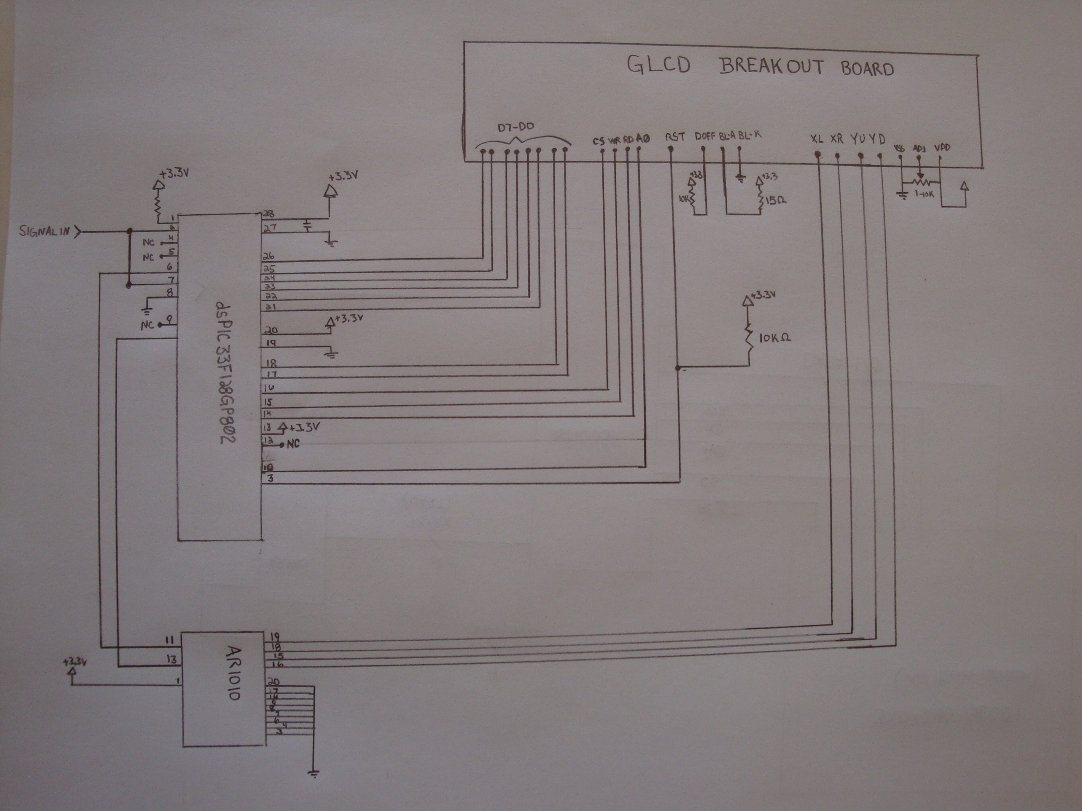
To achieve this project, the initial concept involves sampling an input using an Analog-to-Digital Converter (ADC) at consistent time intervals and subsequently displaying the waveform on a graphic LCD. Adjusting the time scale can be done by modifying the...
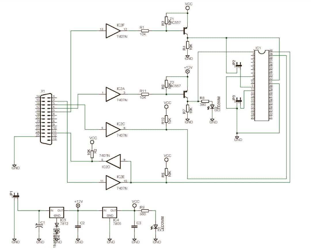
The SCHAER+ programmer is a programmer for PIC18 family from a PC parallel port (LPT). It is derived from the SCHAER programmer I used to download my projects in PIC1684. The SCHAER+ programmer should be improved to use a...

This circuit utilizes a PIC microcontroller and an internal 1 kHz sinewave table to generate an accurate sinewave. It requires only a few external components for filtering. The sinewave benefits from high frequency accuracy due to its generation from...
Pin 3 defines the Display type: Common Cathode or Common Anode. Connect this pin to GROUND if you are using common cathode 7-segment led displays. To use common anode displays, connect it to VCC (positive). Pin 4 is the...
This design was never completely finished, so consider it to be in the very early experimental stage. I don`t sell kits, programmed PLD`s, or provide support for this project, and I will never be published. But if you want...
In certain scenarios, a portion of application code may be stored in the Flash/EPROM version of the 8031 microcontroller, while the remaining code resides in an external EPROM, particularly in expanded systems. The introduction of the 8051 Programmer serves...