
dual supply 15v based transistors
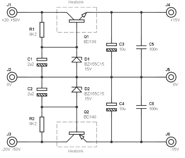
The circuit in question serves as a dual polarity power supply, which is essential for many electronic applications, particularly in audio amplification where both positive and negative voltages are required for proper signal processing. The power supply is capable of delivering a regulated output of +/- 15V, which is typically used to power operational amplifiers, analog signal processing circuits, and other components that require dual polarity voltages.
The schematic includes a series of transistors configured in a push-pull arrangement, allowing for efficient voltage regulation and current handling. The use of transistors provides advantages such as thermal stability and the ability to handle varying load conditions without significant performance degradation. The circuit may also incorporate additional components such as capacitors for filtering and stabilizing the output voltage, as well as diodes for protection against reverse polarity and voltage spikes.
To integrate this circuit into an existing audio amplifier, it is important to ensure that the input voltage supply is compatible with the specified voltage levels of +20V/-20V or +50V/-50V. The output from the dual polarity power supply should connect to the appropriate points in the amplifier circuit, ensuring that the voltage levels are correctly applied to the operational amplifiers or any other components requiring dual supply voltages.
Additionally, careful consideration should be given to the layout of the circuit to minimize noise and interference, which can be critical in audio applications. Proper grounding techniques and the use of decoupling capacitors can help achieve a clean power supply, enhancing the overall performance of the audio amplifier.
In summary, the integration of this dual polarity power supply circuit into an existing audio amplifier can significantly improve its functionality by providing the necessary voltage levels for optimal operation of various electronic components.This circuit is intended to be transplanted into an existing circuit (eg audio amp), which already provides symmetric voltage between + /-20V and + /-50V. The schematic diagram come from circuit: Dual Polarity Power Supply +/- 15V based Transistors power supply.
Go to that page to read the explanation aboutabove power supply related circuit diagram. 🔗 External reference
Related Circuits
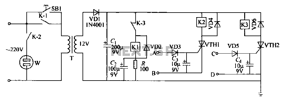
This schematic circuit features two alarm outputs controlled by a timer using thyristors. The system can be turned on or off and will shut down after the power supply is interrupted. It employs a transformer on the primary side...
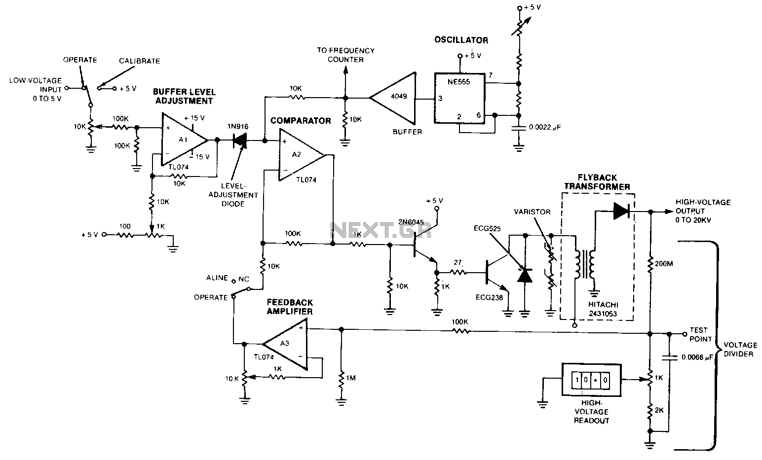
The output voltage varies approximately linearly up to 20 kV as the input voltage is adjusted from 0 to 5 V. A 5-0 potentiometer is used to tune the oscillator, optimizing the output voltage at the frequency of maximum...
LVDT (linear voltage differential transformer) is widely used as a linear position sensor. The AD589 integrated circuit provides a complete solution for LVDT. The Linear Voltage Differential Transformer (LVDT) is a highly precise sensor commonly employed for measuring linear displacement....
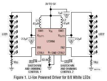
LT3466 is a dual full function step-up DC/DC converter specifically designed to drive up to 20 White LEDs (10 in series per converter) with a constant current. Series connection of the LEDs provides identical LED currents resulting in uniform...
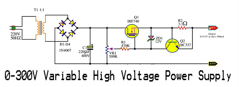
This is a variable high voltage DC power supply circuit that allows for customization of the output voltage ranging from 0 to 311V DC. It includes a current limit protection feature set at approximately 100 mA. The power MOSFET...
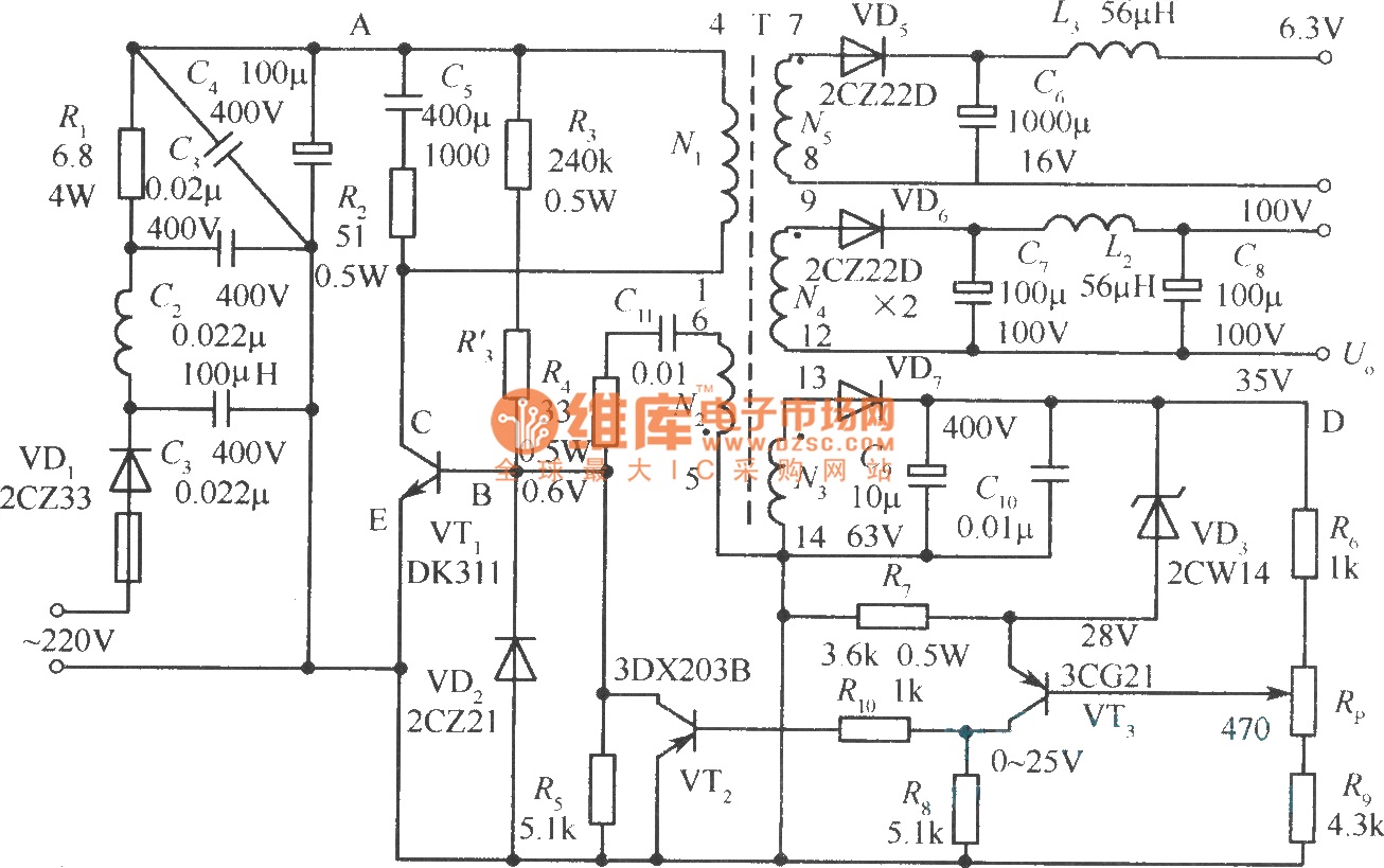
The diagram illustrates the output sampling winding of an isolated switching power supply. In the diagram, T represents a high-frequency transformer; N2 denotes the self-oscillation positive feedback winding; N3 is the error amplifier; VTS is the winding that provides...
Warning: include(partials/cookie-banner.php): Failed to open stream: Permission denied in /var/www/html/nextgr/view-circuit.php on line 713
Warning: include(): Failed opening 'partials/cookie-banner.php' for inclusion (include_path='.:/usr/share/php') in /var/www/html/nextgr/view-circuit.php on line 713