
Output sampling winding isolated switching power supply
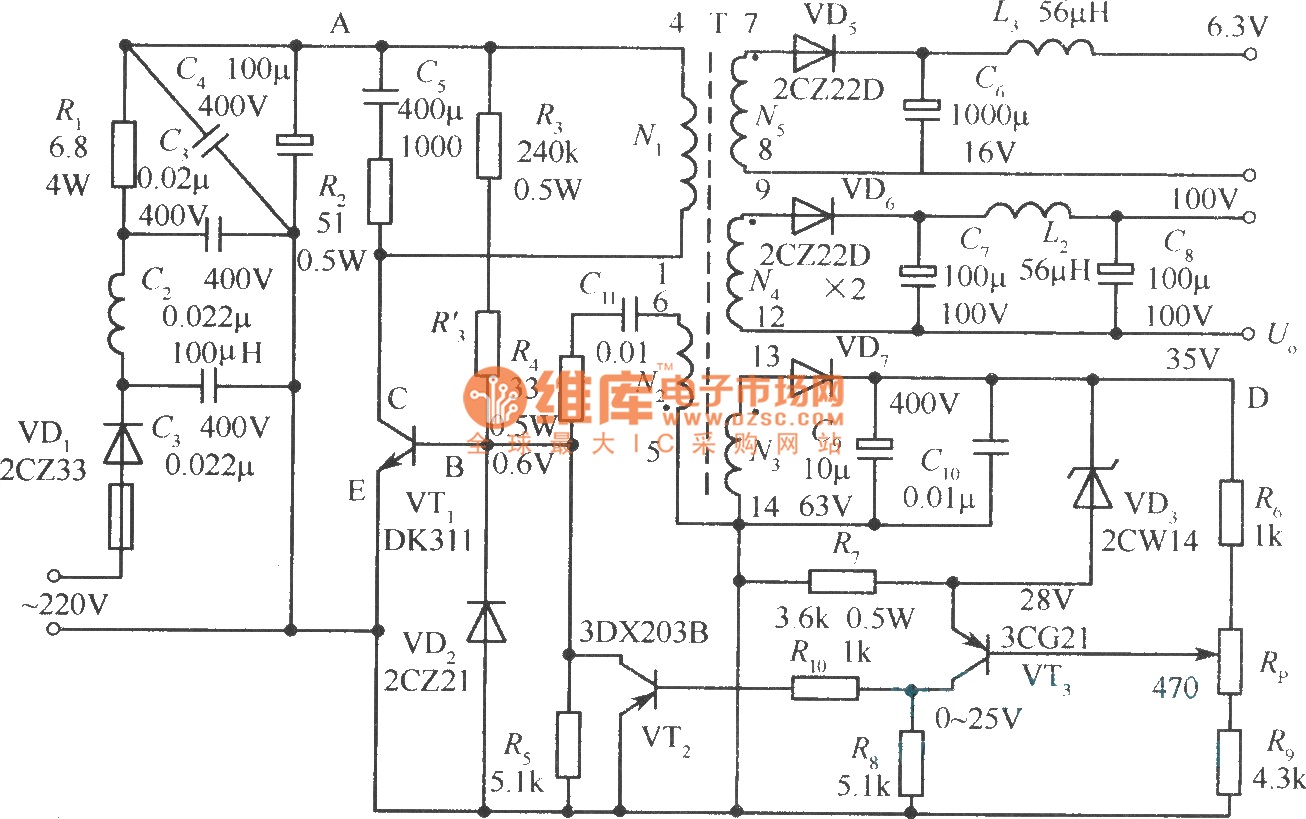
The isolated switching power supply operates by utilizing a high-frequency transformer (T) to transfer energy while maintaining electrical isolation between the input and output. The transformer is designed to operate at high frequencies to reduce the size and weight of the components involved, allowing for a more compact design.
The self-oscillation positive feedback winding (N2) plays a crucial role in initiating and maintaining oscillation within the power supply. This feedback mechanism ensures that the switching frequency remains stable and that the system responds adequately to varying load conditions.
The error amplifier (N3) monitors the output voltage and provides feedback to regulate the output. By comparing the sampled output voltage with a reference voltage, the error amplifier adjusts the duty cycle of the switching signal, ensuring that the output voltage remains within specified limits. This feedback loop is essential for maintaining voltage stability and efficiency.
The sampling signal is derived from the winding VTS, which captures a portion of the output voltage. This sampled signal is used by the error amplifier to make real-time adjustments to the switching operation, enhancing the overall performance of the power supply.
The DC output windings (N4 and N5) are responsible for delivering the regulated DC voltage to the load. The isolation provided by the transformer allows for safe operation, as it separates the high-voltage input from the low-voltage output, minimizing the risk of electrical shock and ensuring compliance with safety standards.
In summary, the diagram represents a sophisticated isolated switching power supply that employs a high-frequency transformer, feedback mechanisms, and sampling techniques to achieve efficient and stable voltage regulation while ensuring electrical isolation between the input and output stages.The diagram shows the output sampling winding isolated switching power supply. In diagram, T is high frequency transformer; N2 is self-oscillation positive feedback winding; N3 is the error amplifier, and VTSis thewinding to provide sampling signal; N4, N5are DC output windings. DC output and the power gridare isolated from each other, because N3, N4, N5.. 🔗 External reference
Related Circuits
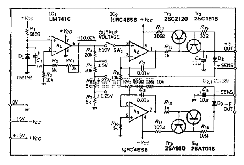
The maximum input voltage is 10V. An operational amplifier (op-amp) is used to provide a reference voltage of 10V, with its stability primarily determined by the characteristics of a temperature-compensated Zener diode (IS2192). The Zener voltage (Vz) can be...

A simple 16-volt switching power supply circuit can be constructed using the provided diagram, which is based on the MAX668 constant-frequency, pulse-width modulating (PWM), current-mode DC-DC controller. This integrated circuit is designed for a wide range of DC-DC conversion...
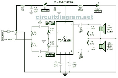
This is the circuit diagram of a USB-powered computer speaker, commonly referred to as multimedia speakers for PCs. The circuit features a single-chip design, operates on a low-voltage electrical power supply, is compatible with USB power from computers, includes...

A simple yet effective circuit to generate a POTS-compatible ringing voltage can be constructed using National Semiconductor's LM4871 audio amplifier IC along with a dozen passive components. This circuit produces a sine-wave output of 1 W at approximately 70...
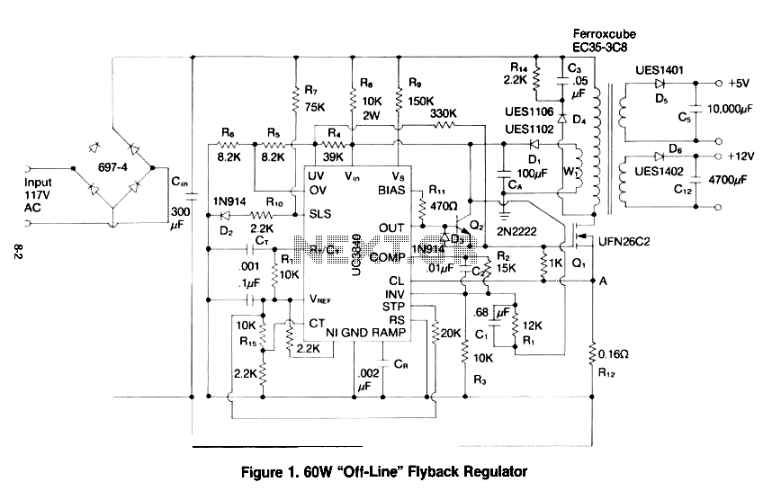
This paper gives a practical example of the design of an off-line switching power supply. Factors governing the choice of a discontinuous flyback topology are discussed. The design uses a pulsed-width modulation (PWM) control scheme implemented with a Unitrode...
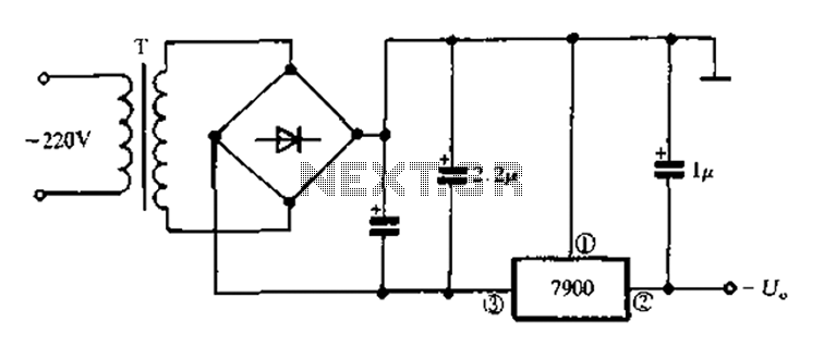
7900 series three-terminal fixed negative output voltage regulator circuit The 7900 series comprises a range of three-terminal fixed negative voltage regulators designed to provide stable output voltages. These regulators are specifically engineered to deliver a consistent output voltage, which is...
Warning: include(partials/cookie-banner.php): Failed to open stream: Permission denied in /var/www/html/nextgr/view-circuit.php on line 713
Warning: include(): Failed opening 'partials/cookie-banner.php' for inclusion (include_path='.:/usr/share/php') in /var/www/html/nextgr/view-circuit.php on line 713