
dual-trace scope switch
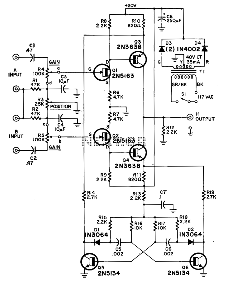
The described circuit configuration involves a switcher output interfacing with an oscilloscope to facilitate the observation of signal characteristics. The switcher output provides a voltage signal that is directed to the vertical input of the oscilloscope, allowing for real-time analysis of the waveform. The external-sync input is utilized to synchronize the oscilloscope's display with the input signal, ensuring accurate timing and phase representation.
The input amplifiers play a crucial role in determining the frequency response of the circuit. With a standard frequency response of 300 kHz, these amplifiers are capable of handling a range of signal amplitudes and frequencies effectively. The gain controls allow for adjustment of the input signal's amplitude, providing flexibility in signal processing. When the gain controls are set to their maximum position, the circuit exhibits an enhanced frequency response capability of up to 1 MHz. This characteristic is particularly beneficial for applications that require the analysis of high-frequency signals, as it enables the observation of rapid signal variations without distortion.
In summary, this circuit design is optimized for high-frequency signal analysis, leveraging the capabilities of the oscilloscope and input amplifiers to achieve precise measurements and observations across a wide frequency range. The synchronization feature further enhances the reliability of the measurements, making this setup suitable for various electronic testing and diagnostic applications.The switcher output goes to the single vertical input of the scope, and a sync line from one of the inputs is taken to the scope's external-sync input. Frequency response of the input amplifiers is 300 kHz over the range of the gain controls. With the gain controls wide open so no attenuation of the signal takes place, the frequency response is up to 1 MHz. 🔗 External reference
Related Circuits
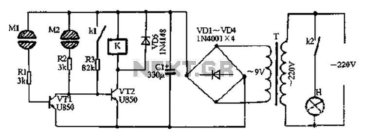
After the power is turned on, 220V AC is stepped down by transformer T. The output is then rectified by the VD1 to VD4 bridge rectifier and filtered by C1 to produce approximately 10V DC voltage for the Darlington...
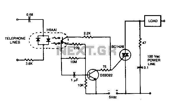
The circuit can operate lamps and buzzers from the 120 V, 60 Hz power line while maintaining positive isolation between the telephone line and the power line. The use of the isolated tab triac simplifies heat sinking by removing...
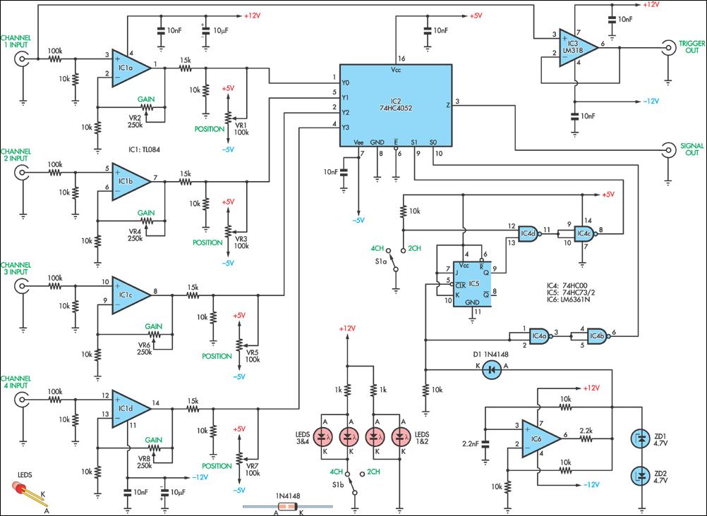
This circuit allows the simultaneous display of four signals using a single channel of an oscilloscope. It effectively switches each of the inputs to the oscilloscope. The circuit utilizes a multiplexer to manage the input signals. A typical configuration would...
This circuit is beneficial for applications where a load must be activated from one location and deactivated from another. Multiple momentary normally open (N/O) switches or push buttons can be connected in parallel. The circuit described facilitates remote control of...
The timing circuit utilizes an electronic switch composed of F1, F2, and VT1 to reduce quiescent current to approximately 1 to 2 A with the 555 timer. Upon initial power-up, the voltage across capacitor C2 cannot instantly change, causing...
As circuit power supply voltages decrease and green energy trends gain popularity, designers should re-evaluate circuits that continuously consume power to reduce overall system power consumption. One such circuit is the "normally-ON" circuit, which can now be redesigned with...