
Four-Channel Oscilloscope Adaptor
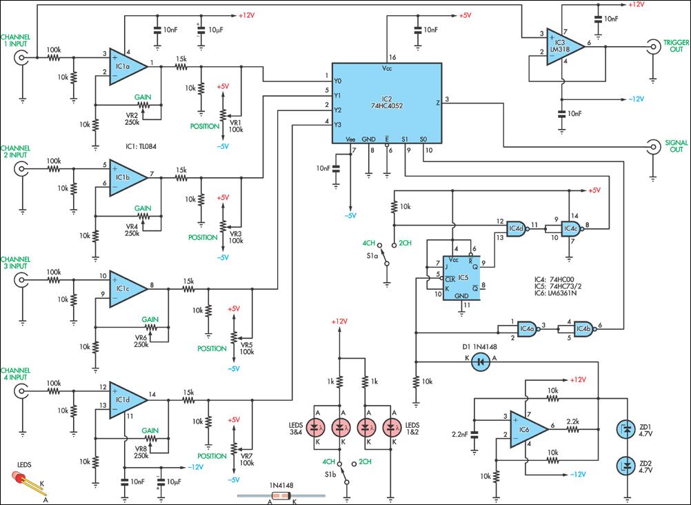
The circuit utilizes a multiplexer to manage the input signals. A typical configuration would involve a 4-to-1 multiplexer, which is capable of selecting one of four input signals based on the binary control signals provided to its select lines. The selected input is then routed to the output, which connects to the oscilloscope channel.
In this design, each of the four signal inputs is connected to the multiplexer. The selection of the input is controlled by a binary-coded decimal (BCD) input, which can be generated using a simple binary counter or manually controlled switches. When the control signals change, the multiplexer switches the selected input signal to the output, allowing the oscilloscope to display the chosen signal.
Additional components may include resistors to protect the inputs and ensure proper signal levels, as well as capacitors for signal conditioning if necessary. The circuit can be powered using a standard DC power supply, ensuring that all components operate within their specified voltage and current ratings.
Overall, this circuit design is efficient for displaying multiple signals with minimal hardware, making it a valuable tool for engineers and technicians who require the analysis of multiple signals without the need for multiple oscilloscope channels.This circuit enables you to display four signals simultaneously using only one channel of your oscilloscope. Essentially, it switches each of the inputs t.. 🔗 External reference
Related Circuits
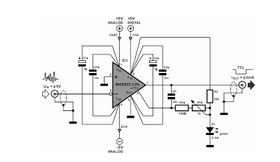
Dynamic flip-flops disregard input pulses that are shorter than 40 ns or do not conform to TTL voltage levels. Consequently, TTL flip-flops are not well-suited for certain applications. Dynamic flip-flops are a specific type of sequential logic circuit that utilize dynamic...
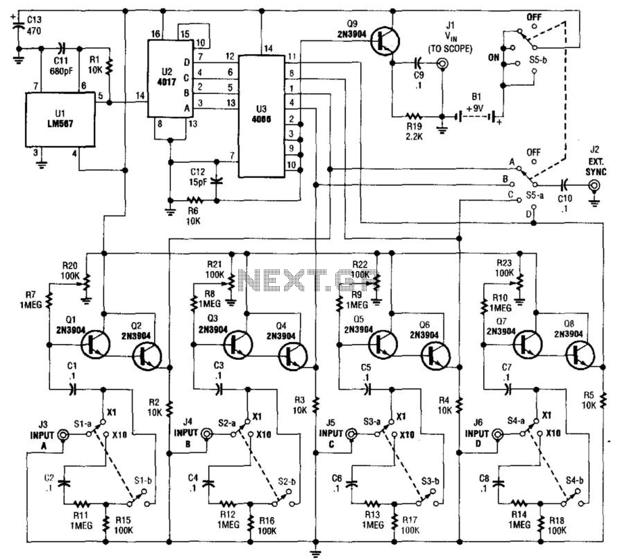
This simple adapter utilizes an oscillator (567) to drive a counter (U2) and a switch (U3) that selects the output of one of four scope preamps (Q1/Q2 through Q7/Q8) and feeds it to buffer Q9 and output jack J1....
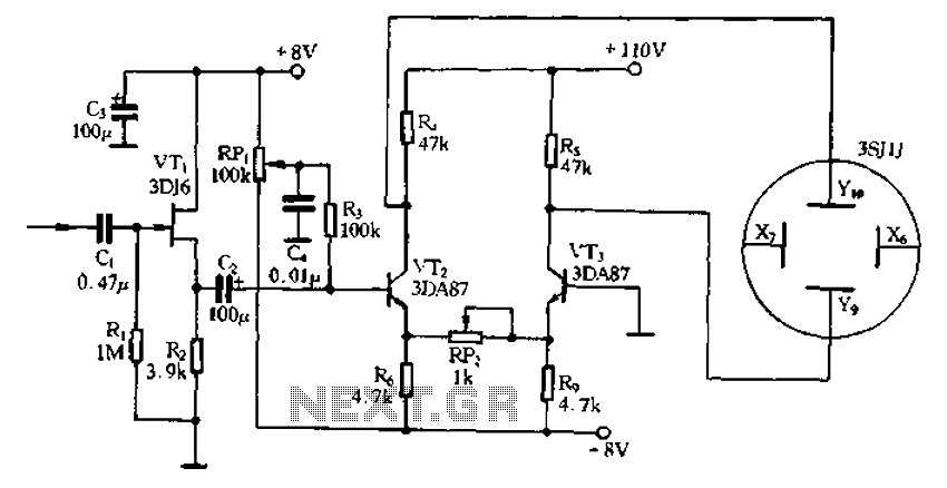
Application of the differential amplifier circuit in a simple small oscilloscope. The differential amplifier circuit is a crucial component in the design of a simple small oscilloscope. This circuit is designed to amplify the difference between two input voltage signals...
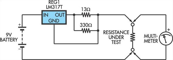
This adapter circuit functions as a 100mA constant current source. It is connected across a low-value resistor, the resistance of which is to be measured, and the resulting voltage drop can then be assessed using a digital multimeter (DMM)....
Many amplifiers have phono inputs for connecting record players to the amplifier. Phono input is designed to take a up to few millivolt signal from phono pickup and amplify it. The amplifier stage does also some equalization based on...
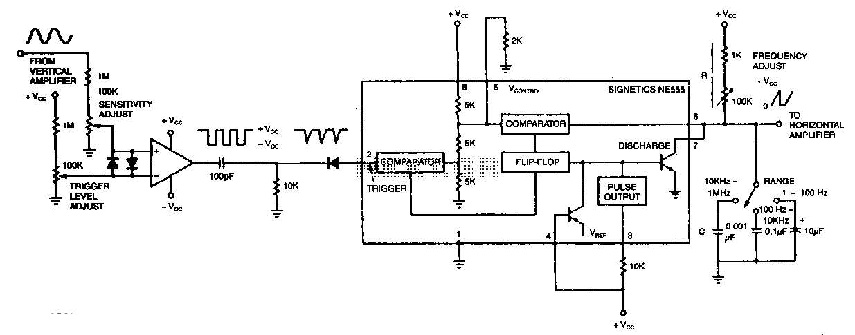
The circuit's input operational amplifier triggers the timer, sets its flip-flop, and cuts off its discharge transistor, allowing capacitor C to charge. When the voltage across the capacitor reaches the timer's control voltage of 0.33 Vee, the flip-flop resets,...