
Two-way touch switch 4
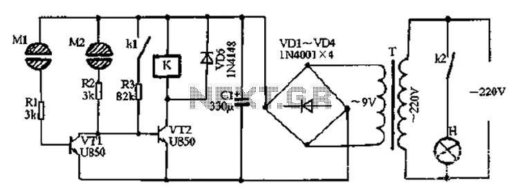
The circuit operates by first converting the high-voltage AC supply into a lower voltage DC suitable for control applications. The step-down transformer T reduces the 220V AC to a manageable level, which is then rectified by a bridge rectifier composed of diodes VD1 through VD4. The output from the rectifier is smoothed out by capacitor C1, yielding a stable 10V DC. This voltage is essential for driving the Darlington pair, which consists of transistors VT1 and VT2.
The Darlington configuration allows for high current gain, making it effective for controlling the relays. Initially, both transistors are in a non-conducting state, meaning that the relays K1 and K2 are open, and the light H is off. The control mechanism is activated when a user presses on electrode pad M2, which sends a base current through resistors R1 and R2 into VT2. This action turns on VT2, which in turn activates relay K, closing the contacts K1 and K2. The closure of K2 energizes lamp H, illuminating it.
To maintain the lamp's illumination, resistor R3 is utilized to create a self-holding circuit. This means that once relay K is energized, it will continue to stay energized even after the pressure on M2 is released. The circuit remains latched until a specific action is taken to turn it off.
When the user touches electrode sheet M1, it causes VT1 to saturate, effectively pulling the base voltage of VT2 down to zero, which switches it off. This action de-energizes relay K, opening contacts K1 and K2, and consequently turning off lamp H. This design allows for a simple yet effective control system for the light, utilizing the properties of Darlington transistors and relay logic to create a user-interactive experience.After the power is turned on, 220V AC by the step-down transformer T, VDI ~ VD4 bridge rectifier and Cl filtered output of about 10V DC voltage for the Darlington circuit and s witch power relay control circuit. Darlington VTI and VT2 are in cut-off state only, two relays normally open contacts K kl and k2 are open, lights H does not shine. Turn on the lights, press a finger pressure at the electrode pad M2, the DC voltage to VT2, inject a base current through resistor finger and R2.
VT2 conduction, the relay K is energized, contacts kl, k2 is closed, wherein k2 lamp is turned on the lamp H H circuit is energized luminous, kl resistor R3 is connected to the circuit so that the circuit self-locking, so that when the finger from the M2, since R3 access relay status remains suction units, lamps H is always light. When the light on, as long as the lower electrode sheet with your fingers Ml. At this time Darlington VTI rapidly saturated conduction, so that the base potential due to VT2 down to zero and turned off, de-energized relay K release, its normally open contact kl, k2 jump, put out the light H off.
Related Circuits
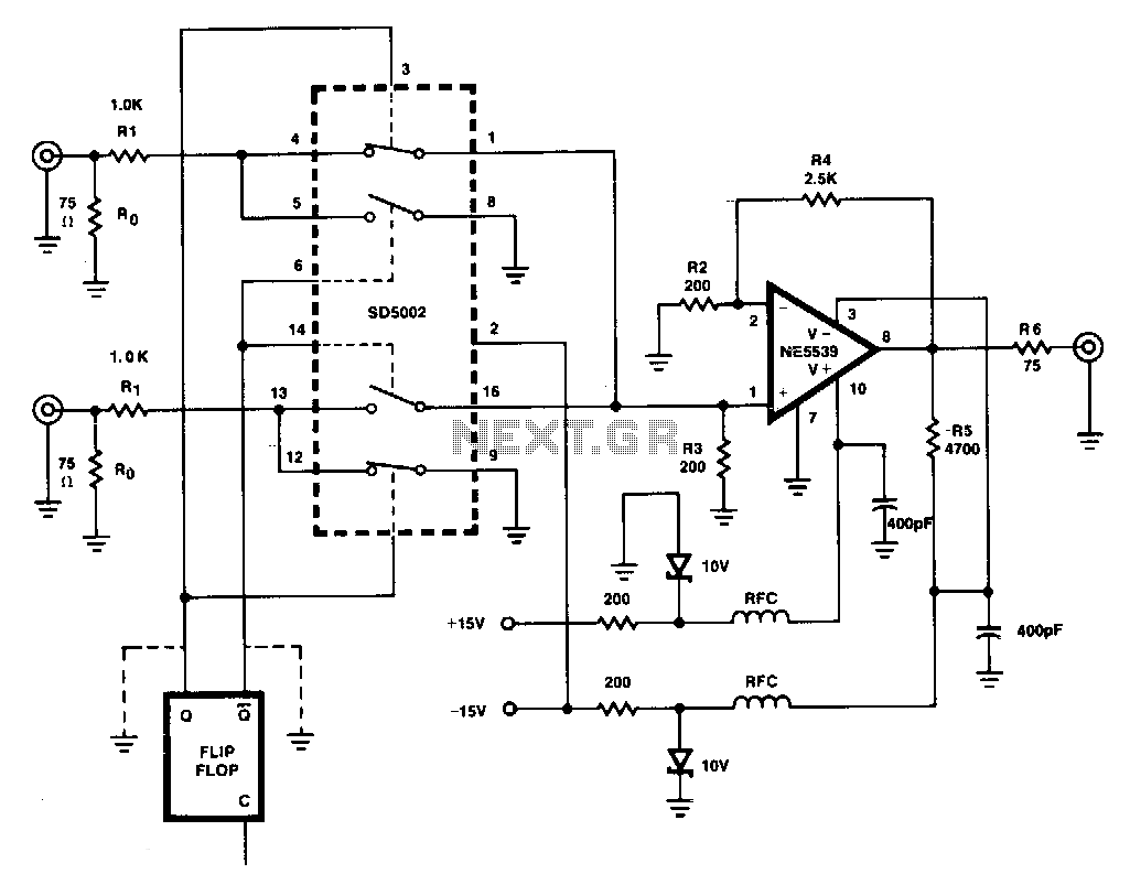
This figure illustrates a one-of-two switch featuring a summing amplifier. The video source's line can be terminated either externally or internally to switch RO. With this termination resistor, a load change of less than 10 ohms will be perceived...
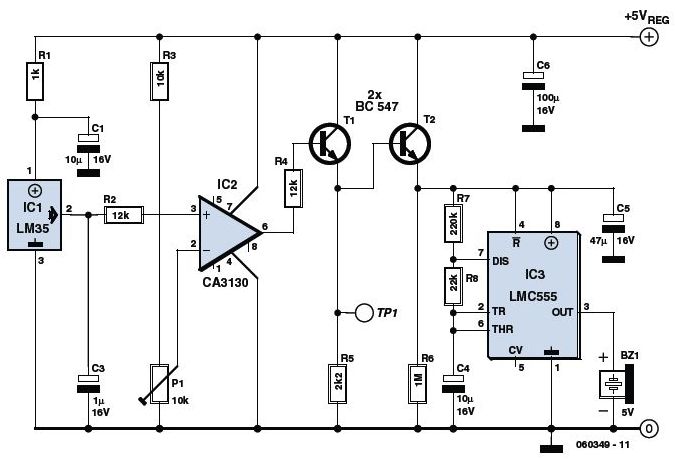
The circuit utilizes a precision integrated temperature sensor, the LM35 (IC1), which provides a linear and directly proportional output in millivolts over a temperature range of 0 to +155 degrees Celsius. This sensor can be incorporated into fire smoke...
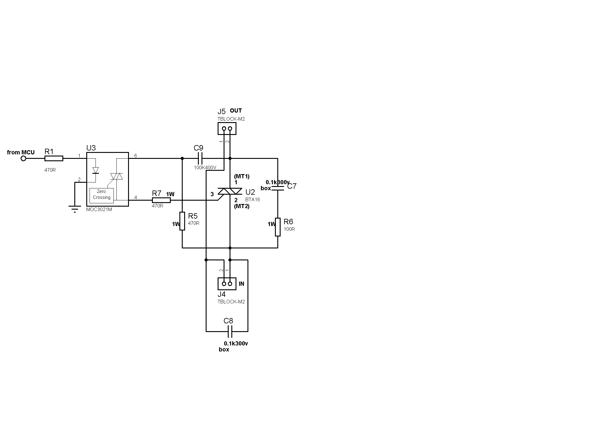
Sufficient snubbering appears to be present around the TRIAC, which should mitigate DV/DT-based switching, preventing the TRIAC from inadvertently turning on due to noise on the gate lead. The issue likely resides on the microcontroller side. When the microcontroller...
This light-sensitive automatic light switch circuit is designed to be connected to the main 220V supply. The circuit will activate a 220V lamp during nighttime. The light-sensitive automatic light switch circuit operates by utilizing a light-dependent resistor (LDR) to detect...
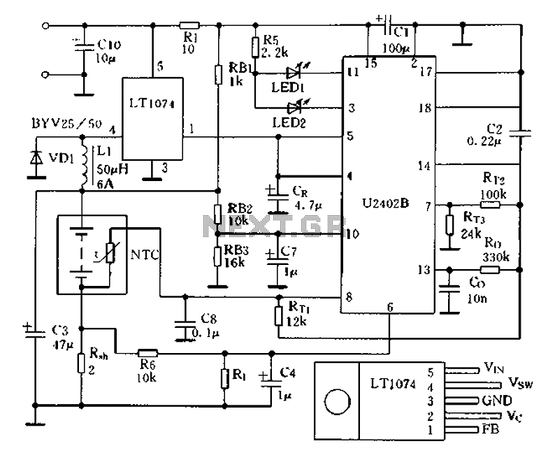
Charging circuit from the DC power supply switching power supply control The charging circuit described is designed to operate with a DC power supply, utilizing a switching power supply control mechanism. This type of circuit is commonly employed in applications...
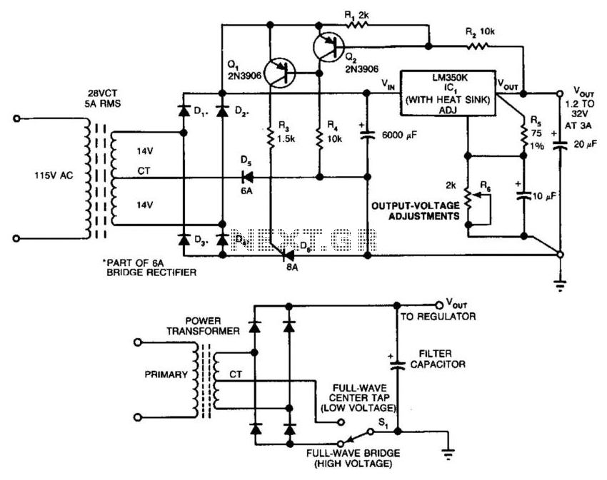
In this circuit, a full-wave bridge is switched to a full-wave center tap to reduce regulator dissipation. SCR D6 switches between configurations. When D6 is off, the circuit is an FWCT rectifier using D1, D2, and D5. It applies...