
Dual Voltage 12V Power Supply
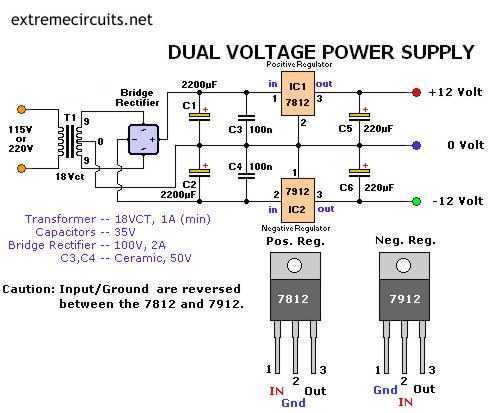
The dual voltage power supply circuit is designed to provide both positive and negative regulated outputs, making it suitable for various applications that require dual polarity power. The circuit utilizes two linear voltage regulators, the AN7812 and AN7912, which are capable of delivering stable output voltages of +12V and -12V, respectively.
The power supply begins with a step-down transformer that converts the high voltage AC input (ranging from 110V AC to 220V AC) to a lower AC voltage, typically between 12V AC to 24V AC. This transformer should be rated for at least 500mA to ensure sufficient current delivery to the load. The secondary winding of the transformer feeds into a bridge rectifier, which converts the AC voltage to a pulsating DC voltage.
Following the rectification, the output is smoothed using capacitors. A large filter capacitor is placed across the output of the rectifier to reduce voltage ripple, ensuring that the voltage supplied to the regulators is as stable as possible. The AN7812 regulator takes the positive side of the rectified output, while the AN7912 handles the negative side. Each regulator requires bypass capacitors at their input and output terminals to enhance stability and transient response.
Typically, a 0.33µF capacitor is connected at the input of each regulator, and a 0.1µF capacitor at the output. These capacitors help filter high-frequency noise and improve the overall performance of the power supply.
The output terminals of the regulators provide the required +12V and -12V, which can be used to power various electronic circuits and devices that operate within this voltage range. This dual voltage power supply is particularly useful in applications such as operational amplifier circuits, analog signal processing, and other electronics requiring dual rail power. Proper heat sinking may be necessary for the voltage regulators to dissipate heat generated during operation, ensuring reliable performance and longevity of the components.The following circuit Diagram of (DUAL VOLTAGE POWER SUPPLY ) can be used for Misc.. application. It requires a few components to built. The most important components of this circuit are REGULATORS. 1 : (AN) 7812 and 2 : (AN) 7912 AN7812 is the Positive Voltage Regulator. It regulates the voltage from (almost) 24vDC to 12vDC (accurate). AN7912 is the Negative Voltage Regulator. It regulates the voltage from (almost) -24vDC to -12vDC. A transformer output must be between 12vAC to 24vAC @ 500mA. Input of transformer (Primary) should be about 110vAc-220vAC. It also include some capacitors to filter the current. 🔗 External reference
Related Circuits
Telephone ringer utilizing 556 dual timers. This circuit generates ringing tones resembling those of a telephone by employing modulated rectangular waves of varying time periods. The telephone ringer circuit employs two 556 dual timer ICs configured to generate modulated rectangular...
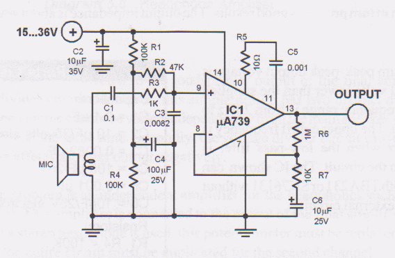
This circuit is a low voltage microphone preamplifier that operates with a 1.5V power supply. It features a reference with a 500 kHz unity-gain bandwidth, functioning as a preamplifier with a gain of 100. The output from this stage...
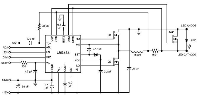
The LM3434 adaptive constant on-time DC/DC buck (step-down) constant current controller can be used to design a simple high-power LED driver application. The LM3434 provides a constant current for illuminating high-power LEDs. The output configuration allows the anodes of...
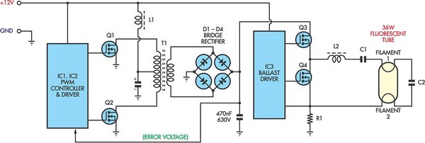
Fluorescent tubes consume significantly less energy compared to incandescent lamps and have a much longer lifespan. They provide diffuse, glare-free lighting and generate low heat output. These attributes make fluorescent lighting a preferred option in commercial and retail environments,...
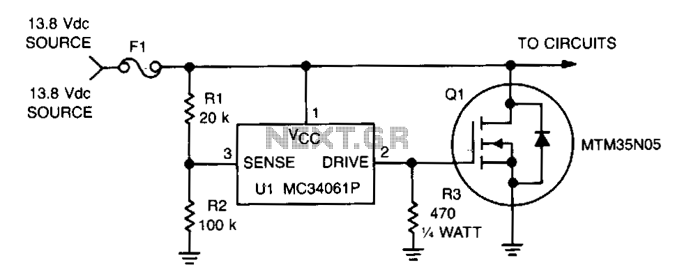
This circuit protects expensive portable equipment against all types of improper hookups and environmental hazards that could cause an overvoltage condition. It operates very quickly and does not latch up; rather, it recovers when the overvoltage condition is removed....

This circuit provides emergency lighting during a power outage. The phototransistor should be positioned to maximize the coupling of both neon light and ambient light into the pellet, without allowing self-illumination from the 6-V lamp. Many circuits of this...
Warning: include(partials/cookie-banner.php): Failed to open stream: Permission denied in /var/www/html/nextgr/view-circuit.php on line 713
Warning: include(): Failed opening 'partials/cookie-banner.php' for inclusion (include_path='.:/usr/share/php') in /var/www/html/nextgr/view-circuit.php on line 713