
phone cut circuit

The Cut Phone Line Detector circuit is designed to monitor the integrity of telephone lines and trigger an alert when a disruption is detected. The core component of the circuit is a MOSFET, which acts as a switch that is activated by the detection of an open circuit condition, indicating that the phone line has been cut.
The circuit typically consists of a voltage divider to monitor the line voltage, a comparator to assess the voltage levels, and the MOSFET which responds to the comparator's output. When the phone line is intact, the voltage across the divider remains within a predetermined range, keeping the MOSFET in the off state. However, when the line is cut, the voltage drops significantly, causing the comparator to change its output state, thereby turning the MOSFET on.
The activation of the MOSFET can be used to drive a relay, which in turn can control various devices such as alarm systems, notification systems, or even motors. It is crucial to ensure that the Cut Phone Line Detector is isolated from other circuits, especially if it is interfaced with a security system. This isolation can be achieved using opto-isolators or relays to prevent any backfeed of voltage that could disrupt the operation of either circuit.
Powering the Cut Phone Line Detector with a separate 9V supply is essential to maintain its functionality and reliability. This dedicated power source ensures that the circuit can operate independently of the phone line voltage, thereby providing consistent performance regardless of the line condition.
In summary, the Cut Phone Line Detector circuit is an effective solution for monitoring phone lines, providing a reliable method for alerting users to potential tampering or line cuts, while ensuring safe integration with other electronic systems through proper isolation techniques.A while ago I got an email asking for the schematic of a circuit to detect cut phone lines. It didn`t take me long to find this circuit in Electronics Now. When the circuit detects that a phone line has been cut, it activates a MOSFET which can be used to drive a relay, motor, etc. It can also be connected to a security system. If the circuit is connected to a security system or other circuit, both circuits must be electrically isolated from each other using an opto-isolator, relay, etc. This also means that the Cut Phone Line Detector must be powered by a seperate 9V supply. 🔗 External reference
Related Circuits

Most ATV (Amateur Television) transmitters operate using a Double Sideband (DSB) signal, while commercial television stations utilize a Vestigial Sideband (VSB) signal. This distinction is leveraged in this converter to utilize the lower sideband, thereby reducing interference from repeaters...
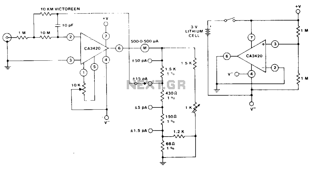
The circuit utilizes the extremely low input current (0.1 pA) of the CA3420 BiMOS operational amplifier. With only one 10 megohm resistor, it achieves a range from ±50 pA maximum to a full-scale sensitivity of ±1.5 pA. Additionally, by...
Many households still have tube-type television sets. Connecting one of these large televisions to a stereo system to enhance sound quality is generally straightforward, as numerous SCART to Cinch adapters are available in accessory stores. However, some television sets...
This AC drill speed controller circuit schematic allows for the control of the drilling speed of a borer or drilling machine. This project is based on the principle that... The AC drill speed controller circuit is designed to modulate the...
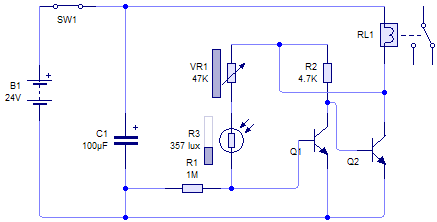
This circuit can provide various utilities, such as an alarm, door opening mechanism, or lighting control for a garden or courtyard, depending on the user's creativity. The operating principle relies on the characteristics of a photoelectric photocell, which alters...
This circuit allows for the independent variation of the on/off times of a 555 timer across a wide range. This capability is not achievable with a conventional 555 timer circuit. The described circuit enhances the functionality of the standard 555...