
dual voltage power supply 12 volt
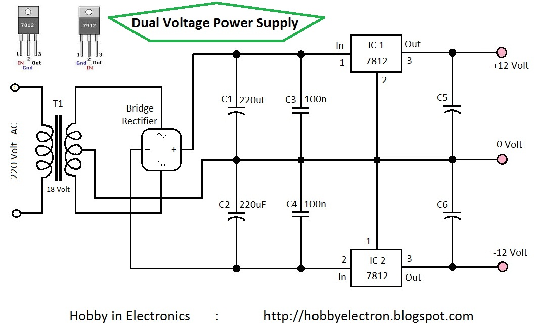
The dual voltage power supply circuit is designed to provide both positive and negative regulated output voltages, specifically 12 Volts DC. This is achieved through the use of two voltage regulator integrated circuits (ICs): the 7812 for positive voltage regulation and the 7912 for negative voltage regulation. The circuit typically takes an AC input from a transformer, which can handle a range of 110 to 220 Volts AC, and steps it down to a lower AC voltage in the range of 12 to 24 Volts AC.
The transformer plays a critical role in this circuit by converting high-voltage AC into a lower voltage suitable for the regulators. The output from the transformer must be rated to supply sufficient current, with a minimum requirement of 500 mA to ensure adequate power for various applications.
To smooth out the output voltage and reduce voltage ripple, capacitors are incorporated into the design. These capacitors act as filters, absorbing fluctuations in voltage and providing a more stable DC output. The use of filter capacitors is essential for maintaining the performance of the power supply, especially in sensitive electronic applications where voltage stability is crucial.
In summary, this dual voltage power supply circuit is a versatile solution for powering various electronic devices that require both positive and negative voltage rails. It is relatively simple to construct and can be adapted for different applications by modifying component values and specifications as needed.Circuit » Home » 7809 » 7812 » 7909 » 7912 » Dual Voltage » Hobby Electronics » Hobby electronics projects » RC filters » REGULATOR » transformer » Dual Voltage Power Supply 12 Volt This is the simple circuit diagram of Dual Voltage Power Supply. It is used for Misc application. This circuit is called regulated power supply. For thi s reason the main component of this circuit is Regulator IC. It also needs few components to built. The regulator 7812 is the positive voltage regulator and 7912 is the negative voltage regulator. It regulates voltage from 24Volt to 12 Volt (DC). The transformer input is 110Volt to 220Volt (AC) and the output must be between 12Volt to 24Volt (AC) and current must be 500mA. In this circuit some capacitors are used as a filter for removing repole. 🔗 External reference
Related Circuits
This circuit generates a double tone police sound and a single tone old ambulance sound. It is typically installed in battery-powered cars and motorcycles. The circuit utilizes a sound generator IC, such as the 555 timer or a dedicated sound...
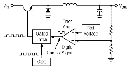
Switching regulator subsystems are designed for use as DC to DC converters. The 3V to 40V DC converter circuit utilizes switching regulators, which are increasingly favored over linear regulators due to the demand for higher conversion efficiency in modern...
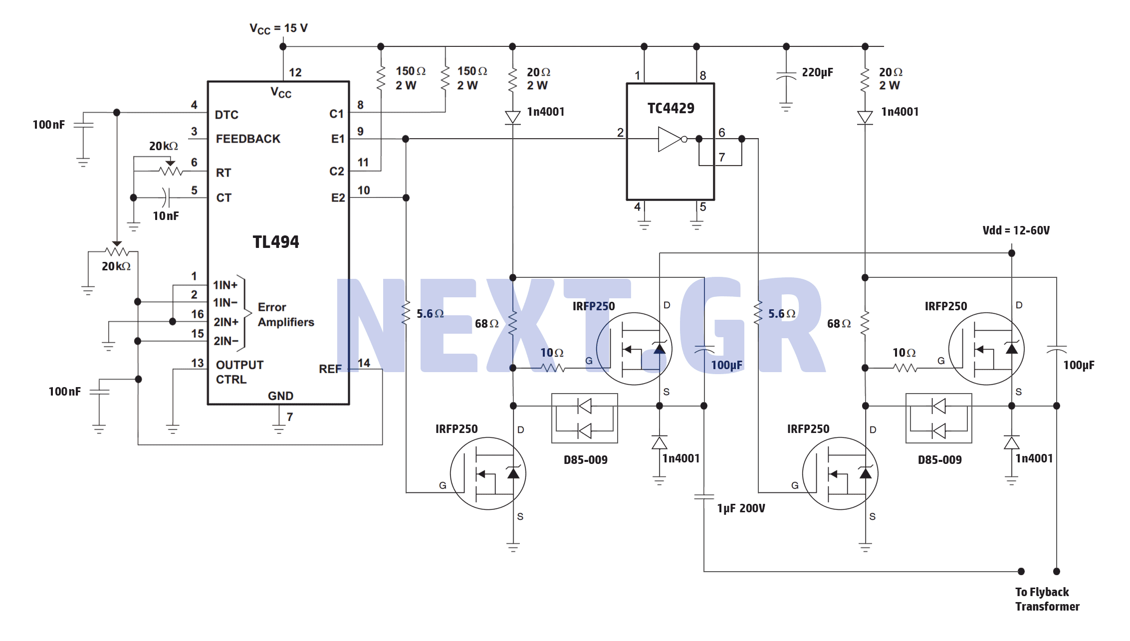
A reliable full bridge driver is essential for driving a flyback transformer. While many flyback driver schematics exist, most lack durability. The well-known Zero Voltage Switching (ZVS) driver, invented by Vladmiro Mazilli, is recognized for its reliability due to...
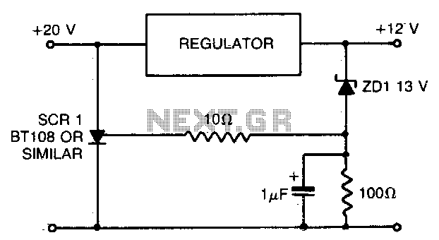
When using a regulated power supply to lower a supply voltage, there is always a risk that a failure in the power supply could result in a significant overvoltage condition across the load. To address overvoltage situations, the circuit...
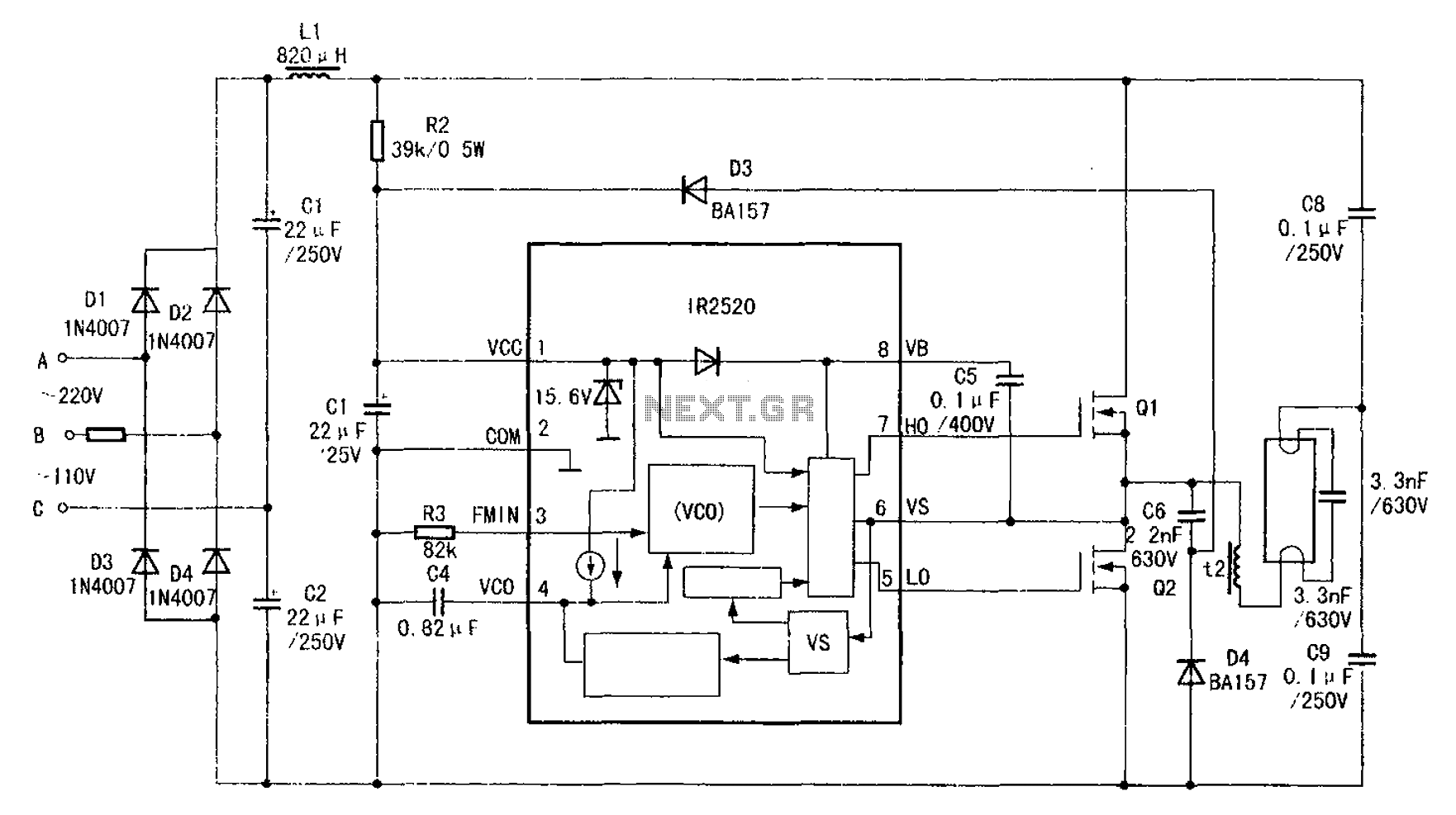
The adaptive zero voltage switching electronic ballast schematic diagram utilizes the IR2520 primarily for driving fluorescent lamps of 40W or less. The parameters of components such as Q1, Q2, L2, and C7 vary depending on the rated power of...
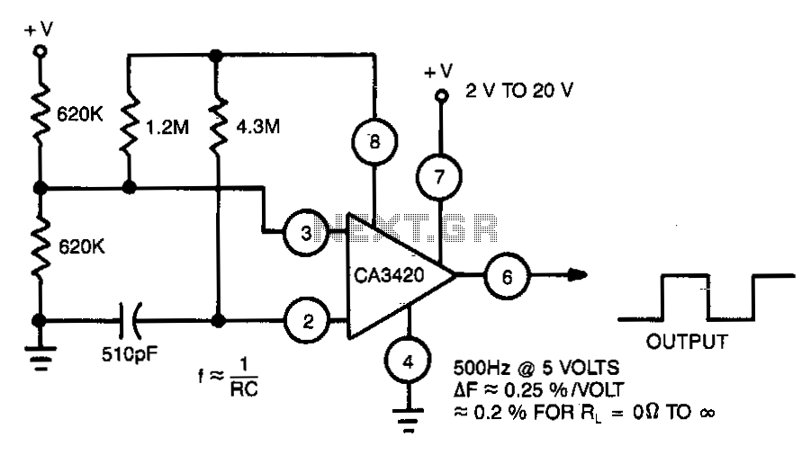
This multivibrator utilizes a CA3420 BiMOS operational amplifier to enhance frequency stability. The output frequency remains largely unaffected by supply voltage variations. Due to the inherent buffering action of pin 6, the frequency shift is approximately 0.2% when the...
Warning: include(partials/cookie-banner.php): Failed to open stream: Permission denied in /var/www/html/nextgr/view-circuit.php on line 713
Warning: include(): Failed opening 'partials/cookie-banner.php' for inclusion (include_path='.:/usr/share/php') in /var/www/html/nextgr/view-circuit.php on line 713