
Adaptive zero voltage switching electronic ballasts

The adaptive zero voltage switching electronic ballast circuit is designed to efficiently drive fluorescent lamps by minimizing switching losses and improving overall power factor. The IR2520 integrated circuit serves as the control unit, regulating the operation of the MOSFETs Q1 and Q2, which act as the main switching devices. These MOSFETs are critical in managing the current flow through the lamp, allowing for smooth ignition and stable operation.
In this schematic, the inductor L2 plays a vital role in energy storage and transfer, influencing the current waveform through the lamp. The choice of inductance is crucial; lower inductance values are preferable for higher power lamps, while higher values are suitable for lower power applications. The capacitor C7 is placed in parallel with the lamp to form a resonant circuit that enhances efficiency and reduces electromagnetic interference.
The circuit's design incorporates feedback mechanisms to adjust the switching frequency, ensuring that the lamp operates at its optimal current rating. This adaptability allows the ballast to function effectively across a range of lamp powers, making it versatile for various applications. The selection of components must be carefully considered to match the specific requirements of the lamp being used, including the rated voltage and current specifications.
Overall, this adaptive ballast design exemplifies advanced electronic control techniques that enhance the performance and reliability of fluorescent lighting systems.Adaptive zero voltage switching electronic ballast schematic diagram: IR2520 is mainly used for driving the fluorescent 40W or less. Rated lamp power different, Q1, Q2, L2 and C7 components such parameters are slightly different. E.g. When the lamp rated power in the 16-28W range. Q1 and Q2 should use 500V, 2A of the MOSFET (eg IRFC420 etc.), L2 inductance values between about 1.8mH and 3.5mH, C7 capacity usually 3.3nF-5.6nF. Lamp greater the power, the inductance value L2 of the smaller, specific debugging determined by the lamp current close to or in line with the rated lamp current.
Related Circuits
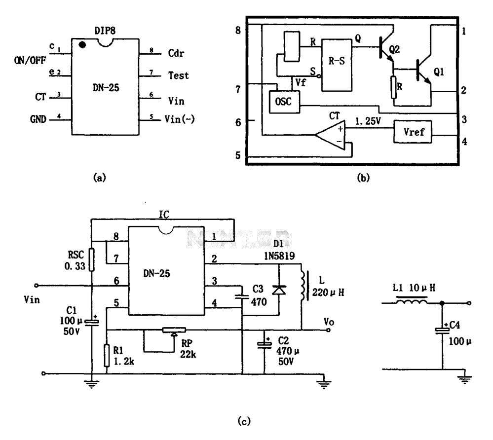
As shown in the figure, the DN-25 IC is a switching power supply. The DN-25 is a monolithic switching power supply device suitable for medium output current applications and a wide voltage range. Its main performance indicators include an...
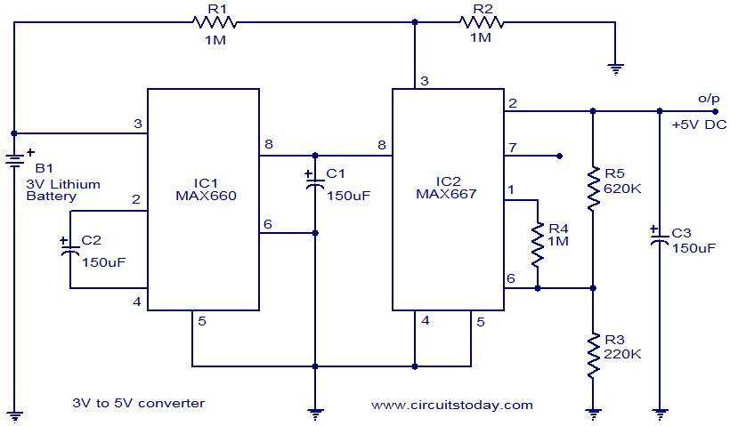
Voltage converter circuit diagram for converting 3 volts to 5 volts using CMOS monolithic ICs MAX660 and MAX667, which functions as a positive voltage regulator. The voltage converter circuit utilizes the MAX660 and MAX667 integrated circuits to step up a...

This AM radio receiver circuit utilizes the TDA1083 radio IC, which is suitable for constructing a simple medium frequency (MF) band radio. The schematic operates within a frequency range of 300 kHz to 3 MHz. The circuit is straightforward...

A simple 5-volt switching power supply electronic circuit project can be designed using the FAN302HL, a highly integrated PWM controller integrated circuit. This IC provides several features that enhance the performance of general flyback converters. The constant-current control of...

This electronic circuit diagram represents an audio power amplifier utilizing the TDA8571J integrated circuit. It is a class-B output amplifier configured in a BTL (Bridge-Tied Load) arrangement, featuring four amplifiers, each with a gain of 34 dB. The main...
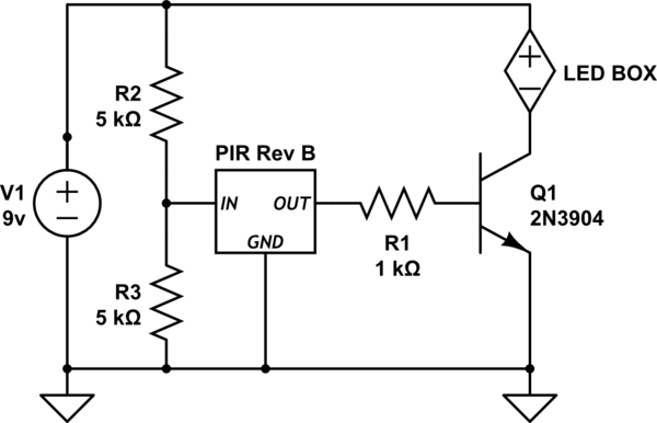
Activate a "black box" of LEDs (operating at 8-9V) when a motion sensor is triggered. The challenge is that the output from the PIR sensor is only 3.3 volts. The schematic provided requires several corrections. Firstly, using a resistor...
Warning: include(partials/cookie-banner.php): Failed to open stream: Permission denied in /var/www/html/nextgr/view-circuit.php on line 713
Warning: include(): Failed opening 'partials/cookie-banner.php' for inclusion (include_path='.:/usr/share/php') in /var/www/html/nextgr/view-circuit.php on line 713