
duracell cpu monitor
To create this analog display for monitoring CPU load, a simple yet effective circuit can be designed using an AA battery and a tester. The display operates by utilizing the tester's ability to visually indicate voltage levels, which correspond to CPU load. The circuit design involves a breadboard setup where the tester is securely mounted to ensure stability during operation.
The first step involves carefully removing the tester from the AA battery while avoiding damage. This is critical as any deformation may hinder the connection process. Once the tester is detached, it should be placed on the breadboard, ensuring that the conductive ink dots align with specific holes marked on the board. This alignment is essential for establishing a reliable electrical connection.
To connect the tester to the circuit, copper wire strands are soldered into the holes aligned with the tester's conductive ink. These wires should protrude slightly to make contact with the ink, ensuring effective transmission of electrical signals. The use of "hairy" copper wire is suggested due to its flexibility and ability to make good contact.
A clear piece of plexiglass is then used to create a stable housing for the tester. This piece is taped to the breadboard, with a hole punched out to allow access to the tester. This design not only secures the tester in place but also allows for easy adjustments and visibility of the display.
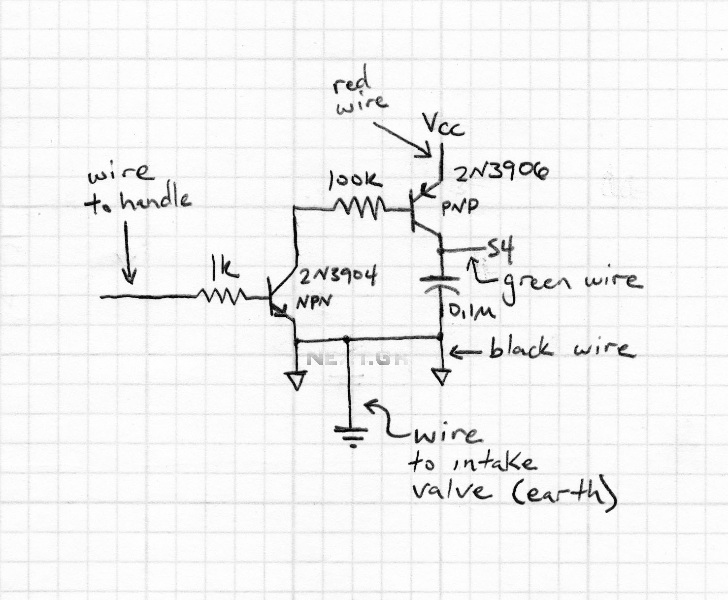
The circuit's schematic includes two switches positioned around 1N4004 diodes. These diodes serve to regulate the voltage supplied to the tester, which may need to be adjusted based on the specific tester's characteristics. By using the switches, one can bypass the diodes, effectively increasing the voltage supplied to the tester, which may enhance the display's responsiveness or accuracy.
Once the circuit is fully assembled, it should be powered with a 3V supply. The final step involves aligning the tester with the copper connectors and closing the plexiglass window. If the connections are properly established, the display should indicate a full yellow reading, signaling that the setup is functioning correctly. It is crucial to handle the tester carefully during this process to prevent damage to the conductive ink.
This setup provides a practical solution for monitoring CPU load on a Linux system, leveraging simple electronic components to create an analog display that is both functional and easy to assemble.Here are instructions to turn such a tester into a not-so-precise analog display to monitor the CPU load on a Linux system, controlled by a serial port. You can build two variants of the display: - An AA Duracell battery with a tester. Energizer testers should work too, but I haven`t tried. I got a pack of Duracell Ultra M3 batteries, product code LR6-MN1500. Cleanly unwrap the tester off the AA battery. Be careful not to pull on any one side too hard, or you`ll warp it and it`ll be that much harder to connect on the breadboard. Personally, I lift both corners, gently unroll it on 3/4 mm, then use a knife and my thumb to finish taking it off the battery with an even pull.
Here`s what it should look like, before trimming the warped bit of the packaging : Here`s the really hard bit : making a somewhat reliable connection between the tester`s conductive ink points and the rest of the circuitry. To do that, place the tester on the breadboard, near the upper edge, and mark out precisely the breadboard holes the wrapper`s white dots fall on.
Spend some time aligning the right white dot (on the "minus" side), as the patch of conductive ink there is very thin and right on the edge of the tester. The dot on the left ("plus") side is less problematic. To make the connectors, solder bits of "hairy" copper wire (like that found on common mains electrical cords) in the holes you marked, and leave the "hairs" sticking out where the tester will be installed.
They`ll help make a correct electrical contact with the tester`s conductive ink. Cut out a piece of clear plexiglas from the CD case, tape one edge to the upper edge of the breadboard, and punch a small hole near the bottom edge. This makes a window to hold the tester and press it flat against the breadboad and the connector. Solder the circuit`s components at the bottom of the breadboard, under the window (there should be about 3 cm worth of breadboard left there).
Here`s the circuit`s schematic: Notice the 2 switches around the 1N4004 diodes : those diodes are there to reduce the voltage fed to the tester, but depending on the individual tester and the quality of the contacts with the conductive ink, you might need to overload the tester a bit to reach 100%, or make it more reactive. With the switches, you can short one or both diodes, adding 0. 6V per shorted diode. Once the circuit is done, feed it 3V and close all the switches. Then carefully align the tester on its connectors, flip the window closed and short pins 4 and 5 of the optocoupler : if the connections are good, the display should very quickly turn completely yellow.
If it does, unshort the pins quickly or you`ll fry the tester (and possibly the window`s plexiglas). Aligning the tester on the connectors is not easy to do, take your time to avoid stripping the conductive ink. Once you have good connection, insert a small metal wire through the hole at the bottom of the window and through the breadboar
🔗 External reference
Related Circuits

A simple heart-beat transducer can be constructed using an infrared LED and an infrared phototransistor. This system operates on the principle that skin serves as a reflective surface for infrared light. The infrared reflectivity of the skin varies depending on...

As shown in the figure, D187 is a UART with its RX/TX signals connected through optocouplers N21, N22, and N29, providing complete optoelectronic isolation for the RS-485 communication interface receiver/transmitter D28 and microprocessor D211. D197 serves as a generator,...
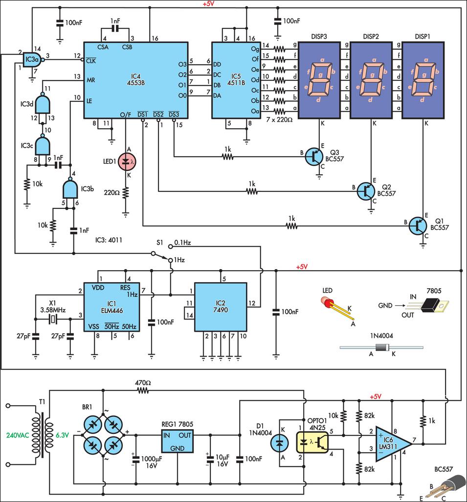
This is a simple frequency counter designed to monitor the 240VAC mains supply. It has a frequency range of 0-999Hz, making it suitable for use with 400Hz equipment as well. Standard TTL/CMOS logic is utilized for the counters and...
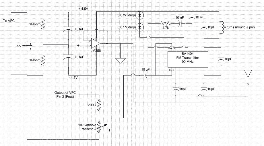
V_logic is connected to the power supply Vs and all ground are connected to the negative terminal of the battery. Fout is a square wave of varying frequency with a maximum amplitude of Vs. A voltage divider is needed...
If a page name is not selected by pressing the button, the previously selected page name continues to be used. The value is stored in EEPROM and may be changed at any time. When the unit is first powered...
The ADM1066 from ADI Company is a monitoring device designed to manage various configurable sequencing applications. It features 12 ADCs and 6 8-bit DACs with a voltage output precision exceeding 0.5% at 25 degrees Celsius. This device is primarily...