Heartbeat monitor
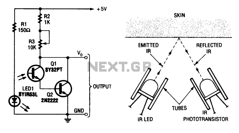
A simple heart-beat transducer can be constructed using an infrared LED and an infrared phototransistor. This system operates on the principle that skin serves as a reflective surface for infrared light. The infrared reflectivity of the skin varies depending on the blood density within it, which fluctuates with the heart's pumping action. Consequently, the intensity of infrared light reflected by the skin—and subsequently detected by the phototransistor—correlates with each heartbeat.
The circuit design consists of an infrared LED positioned to emit light towards the skin surface, while the phototransistor is aligned to detect the reflected infrared light. When the heart pumps, the blood flow changes the density of blood in the skin, affecting its reflectivity. This variation in reflectivity results in a corresponding change in the amount of infrared light that is reflected back to the phototransistor.
In practical implementation, the circuit may include additional components such as resistors to limit current through the LED and to set the biasing for the phototransistor. A microcontroller or an analog signal processing unit can be used to interpret the phototransistor's output, converting the detected signal into a readable heart rate.
To enhance accuracy, the design may incorporate filtering techniques to reduce noise and improve signal clarity. Additionally, calibration may be necessary to account for individual differences in skin reflectivity. The output can be displayed on an LCD or sent to a computer for further analysis, making this simple heart-beat transducer a versatile tool for health monitoring applications.? simple heart-beat transducer can be made from an infrared LED and an infrared phototransistor. ?t works because skin acts as a ref1ecti?e surface for infrared light. The lR ref1ecti?ity of one's skin depends ??? the density of blood in it. Blood density rises and falls with the pumping action of the heart. 80 the intensity of infrared ref1ected by the skin (and thus transmitted to the phototransistor) rises and falls with each heartbeat.
