
DX Audio Filter Circuit
Universal radio receivers are designed to operate over a broad frequency range, making them versatile for various applications. However, for radio amateurs, the wide bandwidth may not provide the necessary selectivity required for effective communication. Models that feature narrower bandwidths are often preferred as they can filter out unwanted signals and reduce interference, allowing for clearer reception of specific frequencies.
In a typical schematic of a universal radio receiver, several key components are involved in achieving this functionality. The front end of the receiver usually consists of an antenna, which captures radio waves, and a radio frequency (RF) amplifier that boosts the signal strength. Following the RF amplifier, a bandpass filter is employed to select the desired frequency range, effectively narrowing the bandwidth. This filter can be implemented using passive components such as capacitors and inductors or active components like operational amplifiers.
Next, the signal is fed into a mixer stage where it is combined with a local oscillator signal. This process shifts the frequency of the incoming signal to an intermediate frequency (IF), which is easier to process. The IF stage typically includes additional amplification and filtering to further enhance the signal quality.
After the IF stage, the demodulation process occurs, where the audio or data signal is extracted from the modulated carrier wave. This can be accomplished using various demodulation techniques, depending on the modulation type (AM, FM, SSB, etc.). Finally, the output stage includes audio amplifiers and speakers or headphones, allowing the user to hear the received signals.
In summary, while universal radio receivers offer broad frequency coverage, models with narrower bandwidths are often more suitable for radio amateurs, providing improved selectivity and signal clarity through a well-designed electronic schematic that includes key components such as RF amplifiers, bandpass filters, mixers, and demodulators.Most universal radio receivers have a very wide bandwidth that is not particulary for radio amateurs. The better models with narrower bandwith are almost a.. 🔗 External reference
Related Circuits
Developed as an interface between the General Instruments AY-3-8500-1 TV game chip and the antenna terminal of a TV set. Adjust capacitor C1 to the frequency of an unused channel to which the receiver is set for playing games....
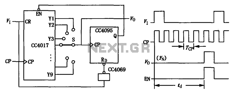
CC4017 counter/distributor featuring a circuit diagram of the delay. The CC4017 is a decade counter and distributor that counts from 0 to 10, providing ten output states. It is commonly used in various digital applications for counting purposes, such as...
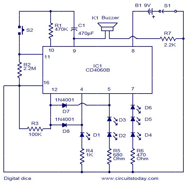
This is a simple and easy-to-construct digital dice circuit. The circuit is based on a single IC, CD4060B. The dice consists of six LEDs marked D1 to D6. The number of LEDs glowing indicates the numeral. The heart of...
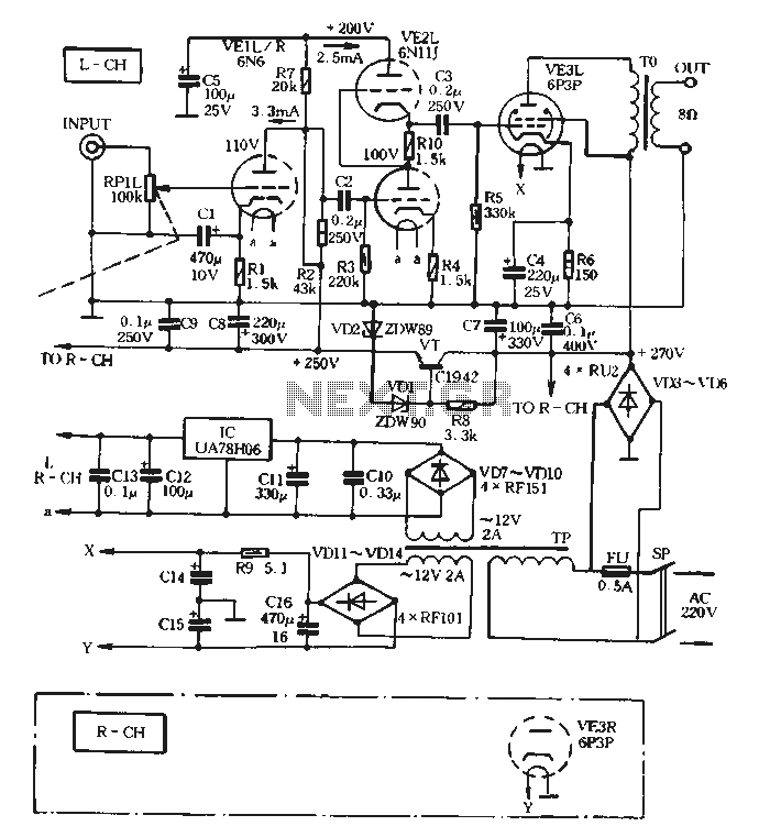
The VE1 preamplifier utilizes a low muscle, low resistance double triode 6N6 configuration, with separate halves for the left and right audio channels. The design operates within the CPI framework. It promotes the use of high-level VE2 household low...
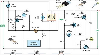
This circuit is designed to switch power to a Peltier cooler in a vehicle. Power is supplied to the load from the vehicle's battery when the ignition switch is on and from an SLA auxiliary battery when the ignition...
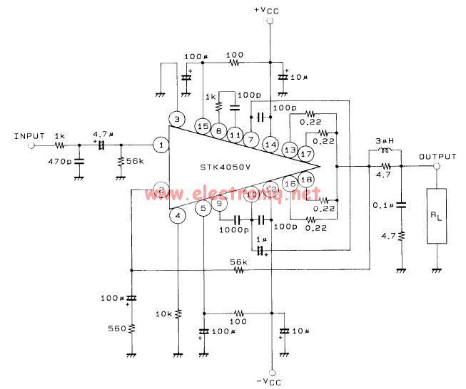
This 200-watt audio amplifier circuit diagram is based on the STK4050V high-power audio amplifier IC, designed to deliver up to 200 watts of audio power on a single channel. The STK4050V 200-watt audio amplifier circuit is pin-compatible with other...