
Dynamic Bass Boost

The Dynamic Bass Boost feature in this Philips radio is implemented through a passive filter circuit, which is designed to enhance the audio experience by compensating for the human ear's frequency response characteristics. The circuit operates by adjusting the gain of lower frequencies based on the volume level, effectively making the sound richer at low volumes and maintaining clarity at higher volumes.
The primary components of the circuit include two capacitors and two resistors, which form the basis of the filter. The configuration allows for the generation of a transfer function that can be analyzed to understand its frequency response. The use of a rotary logarithmic potentiometer for volume control indicates a sophisticated approach to audio adjustment, ensuring that the perceived loudness aligns with the logarithmic nature of human hearing.
The signal path begins at the input (Ui), where audio signals enter the filter circuit. The capacitors play a critical role in shaping the frequency response; when the Dynamic Bass Boost feature is engaged, capacitor C2 is shorted to ground, altering the impedance seen by the audio signal. This action allows the circuit to selectively boost certain frequencies while attenuating others, particularly in the lower range, which is less perceptible to the human ear at lower volumes.
The analysis of the circuit's frequency response reveals notable characteristics. At lower volume settings, the filter maintains a consistent response, ensuring that the audio remains balanced. However, as the volume increases, the transfer function flattens, allowing more high frequencies to pass through, which aligns with the equal-loudness contours that describe how human perception of loudness changes with frequency.
The complexity of calculating the transfer function arises from the interaction between the components, particularly when considering the independence of capacitor responses. The resulting Bode plot illustrates the filter's behavior, showcasing the poles and zeros that define its performance. The first pole and zero are crucial for managing lower frequencies, while the second pair influences the overall slope of the response, allowing for a tailored audio experience that enhances playback quality across various volume levels.
In summary, the Dynamic Bass Boost feature in the Philips portable radio is a well-engineered passive filter circuit that effectively enhances audio playback by compensating for the inherent frequency response limitations of human hearing, providing a richer listening experience across different volume settings.A while ago I was doing some fairly trivial repairs on a Philips portable radio/CD/cassette player. It had a sticker on it claiming that this particular product features something called Dynamic Bass Boost. From the outside this means an extra switch, that when turned on, causes the music to sound better (well, different).
It appears that this is just another marketing name for a filter that tries to compensate for the frequency response of the human ear (sometimes it`s called Loudness, my Sony calls it Dynamic Sound Generator). The idea is that the ear is less sensitive to low and high end of the spectrum and that the sensitivity varies with the volume.
So to compensate you insert a filter into the audio amplifier with a transfer function that matches the inverted ear sensitivity function. I was curious how exactly that filter is implemented, so I disassembled the radio a bit further than it was strictly necessary for repairs and had a look at the circuits.
Judging by the patent application I was expecting something complicated, with active filters and such. This little passive filter circuit is all there is behind that button. It`s implemented on a small circuit board that`s attached directly to the rotary logarithmic potentiometer for volume adjustment (R1 and R2 on the picture) and is duplicated for each channel.
Input is marked Ui and output is Uo. The button merely shorts C2 to the ground. Unfortunately, the capacitors and resistors didn`t have any recognizable markings on them, so I wasn`t able to simply read their values. Instead of measuring each component separately, I measured the circuit`s frequency response using a signal generator with frequency sweep and a digital oscilloscope with a Fourier transform: The potentiometer has a tap at around on third of its range.
As you can see from the circuit, with volume between zero and the tap position the shape of the transfer function is constant while at higher volume settings the transfer function gradually flattens out (compare that with the equal-loudness contours - the curves are flatter at higher volumes). Interestingly, the circuit attenuates lower frequencies even when it`s "turned off". I wonder if this is intentional, to make the difference in sound more noticeable when you turn it on.
From the viewpoint of circuit analysis, it`s pretty complicated to calculate the transfer function analytically without any simplifications. However if you assert that responses of the two capacitors are independent, you get a Bode plot with two poles and two zeros: The first pole and first zero are responsible for the decreased attenuation at the lower frequency range (they disappear when the switch shorts C3), while the second pole and the second zero result in the steady slope towards higher frequencies.
Here`s the simulated filter attenuation versus frequency, this time in the more familiar logarithmic scale. I chose the values of the components so that the shape roughly matches the one I measured on the actual circuit (these are also the values written at the schematic above)
🔗 External reference
Related Circuits
The LM1036 is a DC-controlled circuit designed for adjusting bass, treble, balance, and volume in stereo applications, particularly in car radios, televisions, and audio systems. An additional control input enables the implementation of loudness enhancement. Four control inputs facilitate...
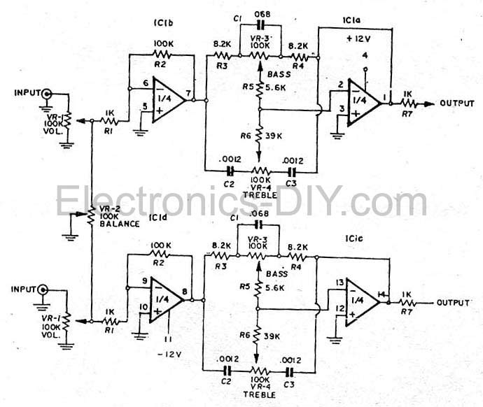
This simple tone control (bass and treble control) can be utilized in various audio applications. It can be integrated into amplifiers, function as a standalone control module, or even be incorporated into new and innovative instruments. The circuit employs...
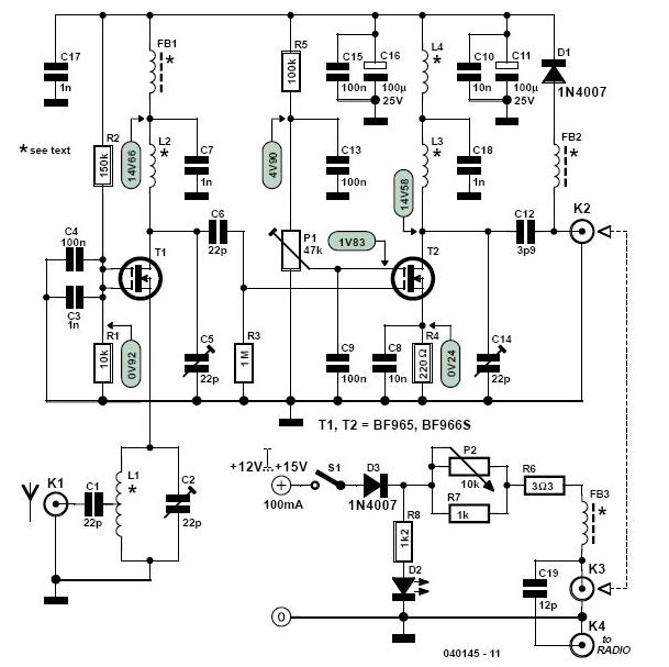
This high-performance two-stage antenna amplifier for the VHF FM broadcast band, when paired with a quality directional antenna, allows for the reception of distant (DX) stations. It significantly enhances the reception of FM signals that may otherwise be considered...
The LM1036 is a DC controlled tone (bass/treble), volume and balance circuit for stereo applications in car radio, TV and audio systems. An additional control input allows loudness compensation to be simply effected. Four control inputs provide control of...
The input impedance of AC-coupled operational amplifier (op-amp) circuits is primarily determined by the resistance that establishes the DC operating point. When using CMOS op-amps, the input impedance is high, reaching up to 10 MΩ in current op-amps. For...
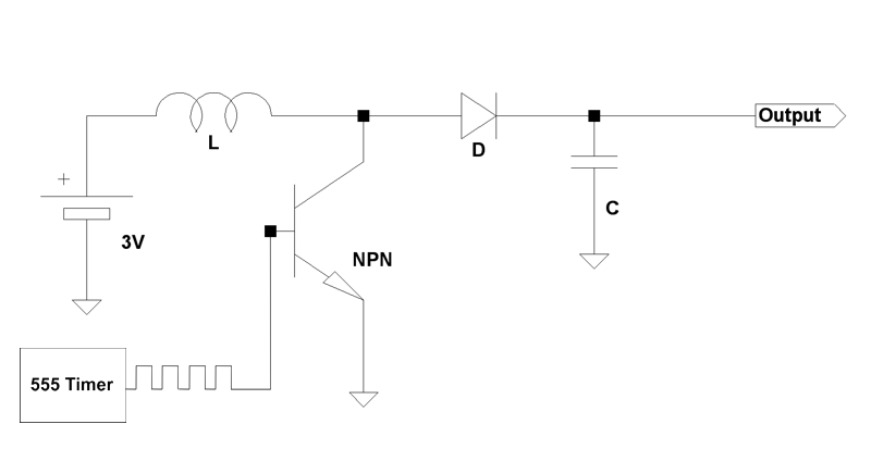
Boost circuits are an effective method for powering microcontrollers. Rather than using multiple AA batteries or a 9V battery (which is typically regulated down to 5V or 3.3V), one can boost the voltage from one or two AA batteries...