
DZ-2 CRV-46152 Aircraft Direction Finding Equipment
The DZ-2 Radio Direction Finder is a notable piece of electronic engineering, reflecting the technological capabilities of its era. Designed primarily for naval aviation, the receiver's architecture includes a robust 24V DC power system, ensuring reliable operation in demanding environments. The high tension (HT) supply, originally sourced from a dynamotor, was critical for the receiver's functionality, allowing it to achieve the necessary signal amplification for effective direction finding.
The ability to operate without the direction-finding loop broadens the receiver's utility, enabling it to cover the entire AM Broadcast Band and receive Non-Directional Beacon signals. This versatility makes the DZ-2 not only a specialized piece of equipment for military applications but also a valuable tool for general radio communication.
The restoration process highlights the importance of maintaining and preserving historical electronic equipment. The challenges faced due to prior modifications and adverse storage conditions underscore the need for careful handling of vintage electronics. The replacement of the original output transformer with a more versatile model capable of supporting both speaker and headphone outputs demonstrates a commitment to usability in a modern context, particularly for educational or display purposes in a museum setting.
Overall, the DZ-2 serves as a testament to early radio technology and its evolution, providing insights into the design considerations and engineering practices of the late 1930s. Its restoration and adaptation for contemporary use ensure that this piece of history remains accessible and functional for future generations.The DZ-2 was built by RCA, Camden NJ, for the U. S. Navy for use in naval aircraft as a Radio Direction Finder. With a contract date of June 30 1939, the receiver is an interesting example of pre-war design. The receiver was powered by the aircraft`s 24v DC power system, with the HT being provided by a separate dynamotor. The receiver can be used without the direction finding loop and covers the NDB`s and the whole AM Broadcast Band. The display receiver had suffered, firstly by some enthusiast`s modifications and secondly by being poorly stored and pressure cooked in a shipping container for 6 years. Aluminium does not like these conditions and the set needed quite a lot of restoration work. As the dynamotor was not available and the filaments had been rewired for 6. 3v AC in a previous life, an external mains supply was used to provide power. HT of 250 volts is satisfactory. The output transformer had been removed as it provided headphone output only. This was subsequently replaced with one capable of speaker and headphone output along with balanced 600 line for use in the museum.
🔗 External reference
Related Circuits
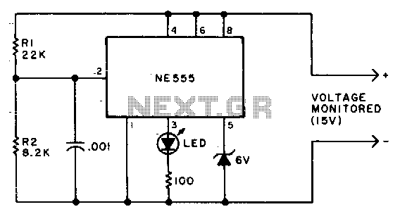
Due to the low duty cycle of the flashing LED, the average current drain is 1 mA or less. The NE555 will trigger the LED when the monitored voltage falls to 12 volts. The ratio of R1 to R2...
The circuit below is designed to be used with the bi-directional lamp sequencer shown above on this same page. Two additional transistors are used to increase the current from the 74HCT138 decoder to control 12 volt 25 watt lamps....

This unit captures the ATV signal by sampling the transmission line with minimal insertion loss. It features two N connectors for input and output connections, while a BNC connector is utilized for the video output. The detected output connects...
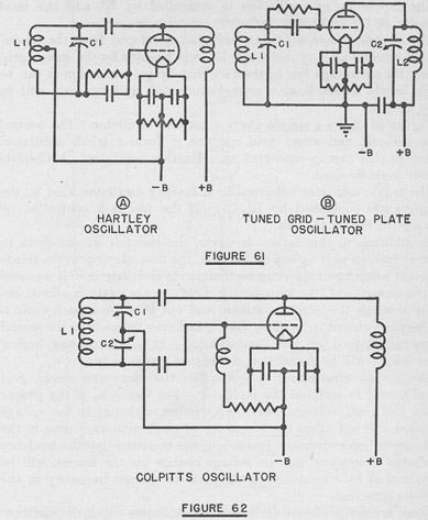
The tuned circuits of capacitance and inductance used in vacuum tube transmitter circuits are often referred to as "tank" circuits, as they serve as reservoirs of RF energy. Blocking capacitors are employed to create a high impedance path for...

A new type of NiMH battery known as HeCell has recently been developed, which is claimed to allow higher discharge rates than the conventional ones (about 12 - 16C). The HeCell NiMH battery represents a significant advancement in battery...

The circuit diagram and detailed explanation of a simple aircraft radio circuit are provided below. The simple aircraft radio circuit typically consists of several key components that work together to facilitate communication between the aircraft and ground stations or other...