
Undervoltage indicator for battery equipment
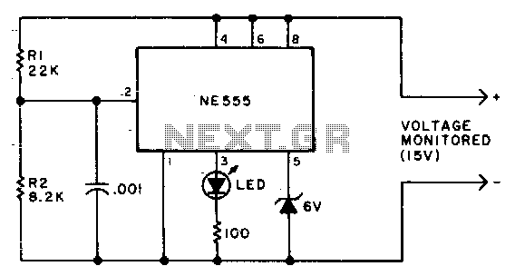
The circuit utilizes an NE555 timer configured in a monostable mode to monitor a specific voltage level. The primary function of this circuit is to illuminate an LED when the voltage drops to a predetermined threshold, specifically 12 volts. The low duty cycle of the flashing LED ensures minimal average current consumption, maintaining it at or below 1 mA. This is particularly beneficial in battery-operated devices where power efficiency is critical.
To achieve the desired voltage monitoring capability, resistors R1 and R2 are utilized to set the reference voltage at which the NE555 triggers the LED. The relationship between R1 and R2 determines the threshold voltage. By adjusting the values of these resistors, the voltage level at which the LED activates can be precisely controlled. This flexibility allows for customization based on different application requirements.
The NE555 timer operates by charging and discharging a capacitor connected to its timing pins, which in turn influences the output state that drives the LED. When the monitored voltage falls to 12 volts, the voltage divider formed by R1 and R2 provides a sufficient voltage to the trigger input of the NE555, causing it to switch the output high, thus turning on the LED.
This circuit design is particularly effective for applications requiring voltage level monitoring, such as battery management systems, where visual indicators for low voltage conditions are necessary. The simplicity of the NE555 timer combined with the adjustable resistor configuration makes this design both practical and efficient for various electronic projects.Due to the low duty cycle of flashing LED, the average current drain is 1 mA or less. The NE555 will trigger the LED on when the monitored voltage falls to 12 volts The ratio of Rl to R2 only needs to he changed if it is desired to change the voltage point at which the LED is triggered. 🔗 External reference
Related Circuits

This circuit diagram represents a logic probe based on a single CMOS integrated circuit (IC). The logic probe indicates three conditions: High, Low, and Pulsing. Additionally, no LEDs will illuminate when the probe input is in a high-impedance state,...
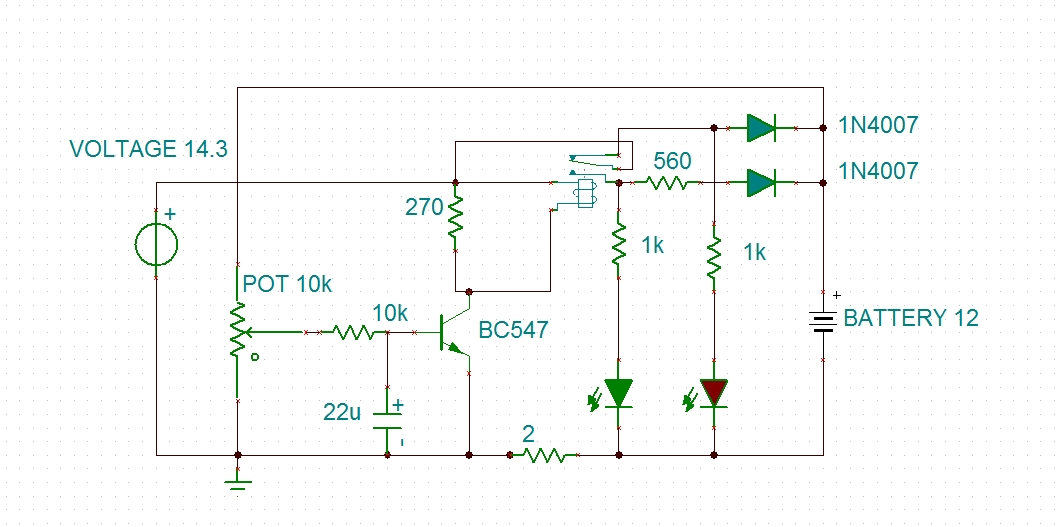
Using a transistor will not yield accurate results, and the adjustment process can become quite tedious. The circuit is technically correct; if the tripping point can be adjusted properly, it may function as intended. Vinod states that he created...
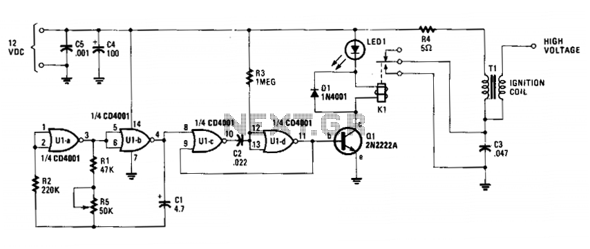
The circuit is fundamentally an auto ignition coil paired with a set of points that perform a similar function. It employs a pulsing circuit constructed from a single CMOS NOR integrated circuit (U1) to open and close relay contacts,...

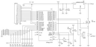
This device is an upgraded version of the PIC16C71 4-digit LED frequency counter and voltmeter. It eliminates several hard-to-find components from the previous model, which have been out of production for some time. The older PIC16C71 has been replaced...
A battery charger can be understood as a device designed to replenish the charge in a battery. An effective charger circuit should provide the necessary resources for efficient and safe battery charging. The AVR-Based Battery Charger utilizes the ATMega...

Unlike lead-acid batteries, one advantage of lithium-ion (Li-Ion) batteries is that they can be charged at a 1C rate initially. This means the charging current can be as high as the rated ampere-hour (AH) capacity of the battery at...