
DZW75-48/5050II input circuit
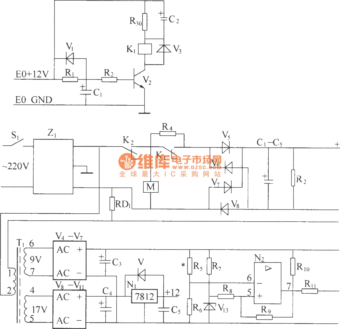
The circuit design integrates several critical components to ensure reliable operation and protection of the system. The Z1 filter plays a pivotal role in mitigating electrical noise and transients, which can adversely affect the rectifier's performance. By using capacitors and inductors in the Z1 filter, both common mode and differential mode noise are effectively attenuated, leading to improved signal integrity and reduced electromagnetic interference.
The relay K2 operates as a protective mechanism, monitoring the AC voltage levels. In the event of over-voltage or under-voltage conditions, K2 disconnects the load, preventing potential damage to downstream components. The use of a current-limiting resistor R4 is crucial for managing inrush currents during startup, ensuring that the system operates within safe limits.
The bridge rectifier is designed to convert the AC voltage to a stable DC output. The choice of diodes within the rectifier is essential, as they must withstand the peak inverse voltage and provide efficient conduction to minimize power losses. The output capacitor bank, connected in parallel, smooths the rectified voltage, reducing ripple and providing a stable DC supply for further processing.
R2, as a leakage resistance, serves to discharge the capacitor bank during shutdown, ensuring safety and preventing capacitor damage from residual charge. The AC current limiting delay circuit is engineered with precision to allow for a controlled startup sequence. This is critical in applications where sudden surges in current can lead to circuit damage or operational instability.
Overall, this circuit schematic illustrates a robust design tailored for AC to DC conversion with integrated protective features, ensuring both operational reliability and safety in various electrical applications.220V (5Hz) alternating voltagepass Z1 circuit filter filtering, then it will send to the connect point of AC over voltage, under voltage protect relay K2. When normal working, K2 connect point should up-close, connect AC 220V voltage to AC current-limiting resistance R4 (after starting up, delay period of time, R1 is short-circuit by K1 connec
t point), send to power frequency bridge rectifier rectifying, get DC 300V output voltage through parallel connection condenser bank smoothed filtering, finish power frequency AC/DV transform. R2 is leak resistance. (2) Z1 circuit filter is used for suppressing and absorbing obstruction of strong pulse to rectifier on electric network, increasing the reliability of rectifier.
At the same time, the good common mode and difference module insertion loss of circuit filter can effectively inhibit inverted output high frequency interfering signal generated by high frequency switching converter, it canisolate rectifier and electric fence, avoid mutual interference. (3) AC over voltage, under voltage protection circuit, AC 220V voltage sended to reducing transformer after through circuit filter filtering.
(4)AC current limiting delay circuit, AC voltage can switch-in machine in normal work range, build time at auxiliary power supply after AC power supply switch-in, andby a period of time delay after auxiliary power supply build, it can make AC current-limiting resistance short-circuit, this period time is AC current limiting delay, it is finish by AC current limiting delay circuit. 🔗 External reference
Related Circuits
The cooling is not only a PC using a small fan with an electronic commutator. A special feature of these fans is that their removal is less dependent on the load. Indicators monitoring the DC component of current may...
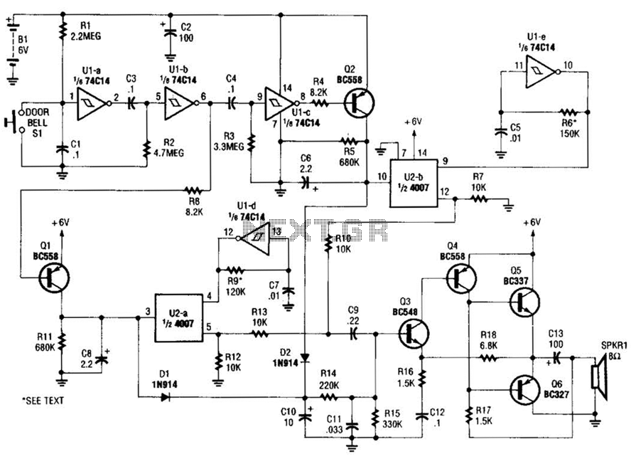
When the doorbell switch is pressed, two monostable stages are sequentially activated, applying bias to a pair of voltage-controlled resistor stages. These stages modulate the outputs from a pair of tone generators. The resulting signals are then fed to...
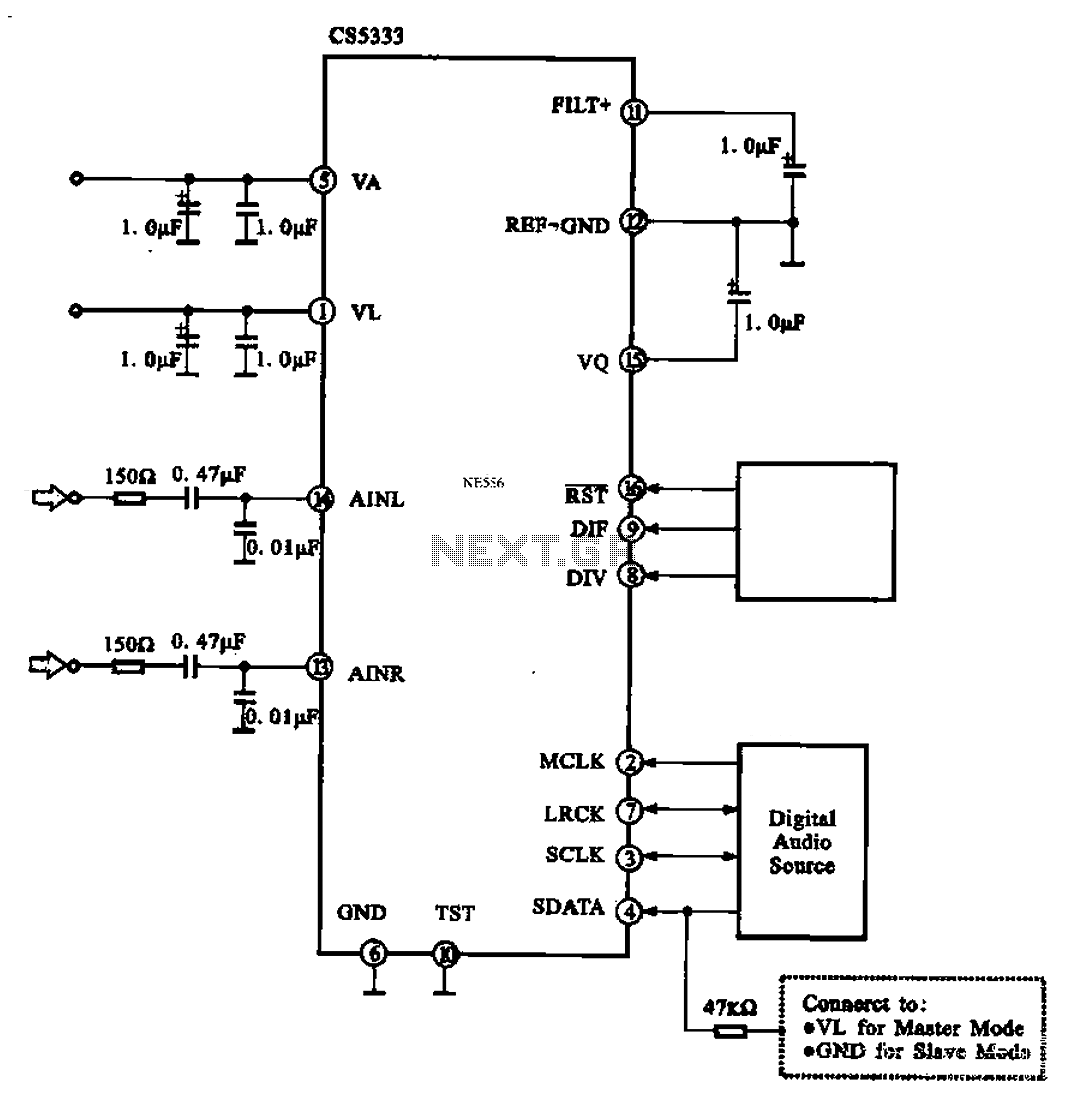
Audio A/D converter circuit configuration using the CS5333 chip, which is a high-performance 24-bit, 96 kHz stereo A/D converter commonly used in digital products. This circuit converts one or more audio signals into a digital signal for processing and...
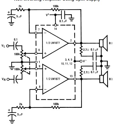
This audio amplifier circuit is designed to deliver 2W per channel continuously into 8-ohm loads. The LM1877 is engineered to function with a minimal number of external components while still offering flexibility for applications in stereo phonographs, tape recorders,...
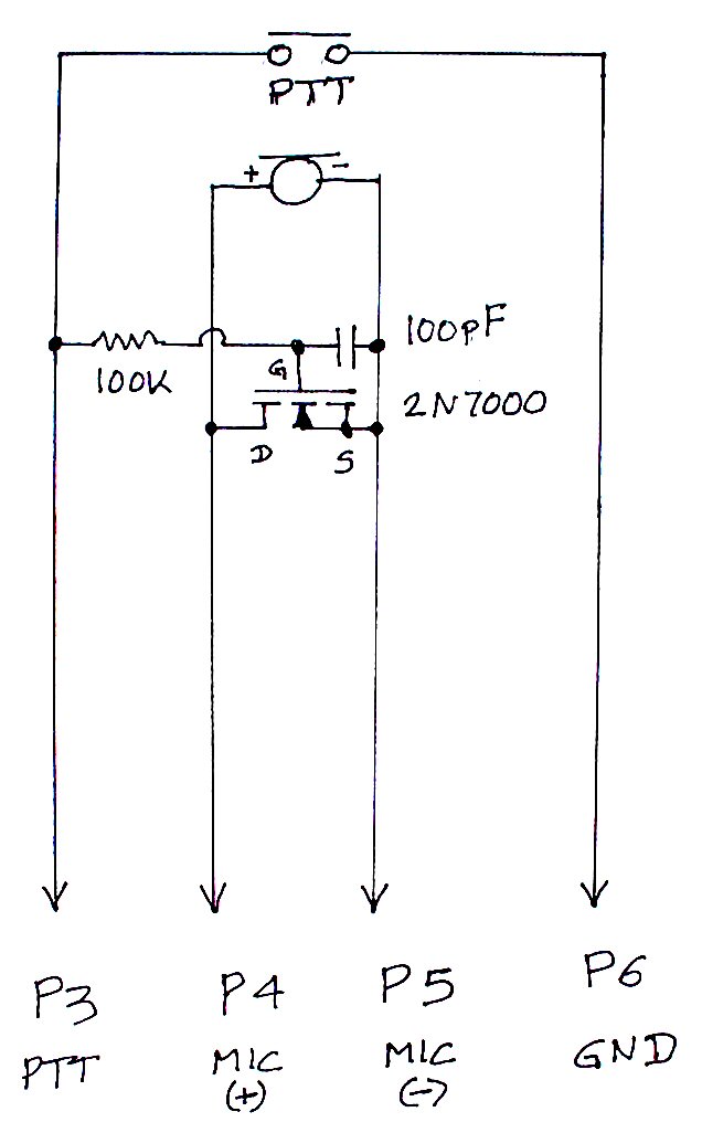
The TS-440S, similar to several other radios, does not mute the microphone when utilizing the rear audio connector for digital modes. Consequently, unless the microphone is unplugged each time digital modes are used, background noise from the shack can...
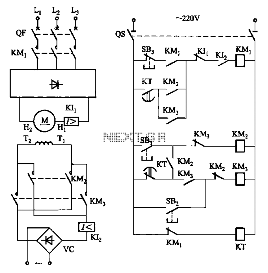
The circuit depicted in Figure 3-193 illustrates a separately excited DC motor. The brake circuit is not activated; therefore, positive reversals occur alternately using a delay action relay, ensuring that the motor reverses direction after coming to a stop. The...
Warning: include(partials/cookie-banner.php): Failed to open stream: Permission denied in /var/www/html/nextgr/view-circuit.php on line 713
Warning: include(): Failed opening 'partials/cookie-banner.php' for inclusion (include_path='.:/usr/share/php') in /var/www/html/nextgr/view-circuit.php on line 713