
Schematic Diagram LM1877 Audio power amplifier circuit

The audio amplifier circuit utilizes the LM1877 integrated circuit, which is specifically tailored for low-power audio amplification applications. The design ensures efficient operation while maintaining sound quality, making it suitable for various consumer audio devices. The output stage of the LM1877 is capable of delivering 2 watts of power per channel, which is adequate for driving typical 8-ohm speakers in home audio systems.
The internal architecture of the LM1877 includes a built-in voltage regulator that stabilizes the power supply, thereby enhancing the amplifier's performance by minimizing noise and distortion that could arise from fluctuations in the power source. This feature is particularly beneficial in portable devices where battery voltage can vary significantly. The common biasing approach for the power amplifiers ensures that the output quiescent point is centered, which optimizes the linearity of the output signal and reduces crossover distortion.
The internal compensation for gains greater than 10 allows the LM1877 to be versatile in various applications, providing a stable frequency response across a range of operating conditions. This characteristic is crucial for maintaining audio fidelity, especially in high-gain scenarios where phase shifts could lead to instability.
Overall, the LM1877 audio amplifier circuit is a robust solution for achieving high-quality audio amplification in compact designs, requiring fewer external components while providing reliability and flexibility across a range of audio applications.This audio amplifier circuit is designed to deliver 2W per channel continuous into 8 © loads. The LM1877 is designed to operate with a low number of external components, and still provide flexibility for use in stereo phonographs, tape recorders and AM-FM stereo receivers, etc. Each power amplifier is biased from a common internal regulator to pro vide high power supply rejection, and output Q point centering. The LM1877 is internally compensated for all gains greater than 10. 🔗 External reference
Related Circuits
The series of light switches is slightly different from traditional designs. These light switches can operate directly on the AC power network. The main components of the circuit include a TRIAC and a Light Dependent Resistor (LDR). The circuit...
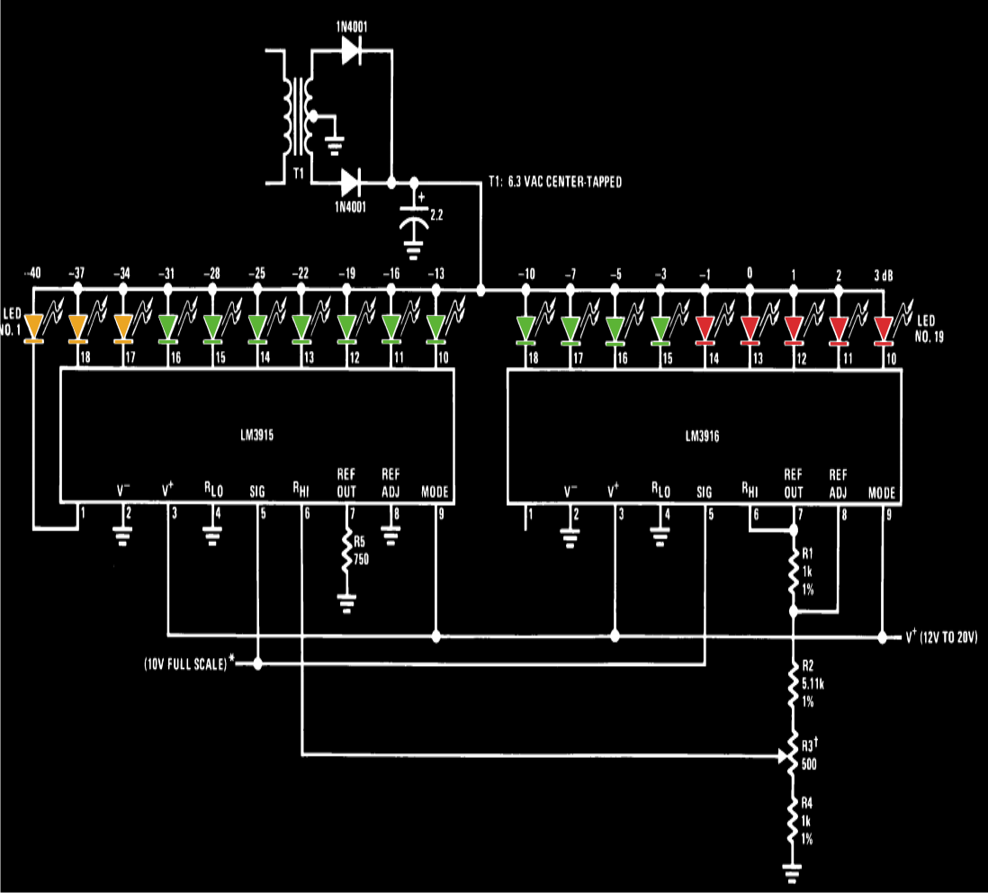
A VU meter, or volume unit meter, is a device used to indicate the music volume output from an amplifier or loudspeaker system. It can also be viewed as a device for displaying the PMPO (Peak Music Power Output)...
Siren Circuit. This circuit generates a sound siren when switch S1 is pressed, increasing the sound frequency as capacitor C1 charges. The sound frequency decreases when switch S1 is released. The siren circuit operates based on the charging and discharging...
Toyota MR2 Exterior Lights Wiring Diagram Manual PDF Download. The Toyota MR2 Exterior Lights Wiring Diagram Manual provides a comprehensive guide for understanding the wiring configurations associated with the exterior lighting system of the Toyota MR2 model. This manual is...
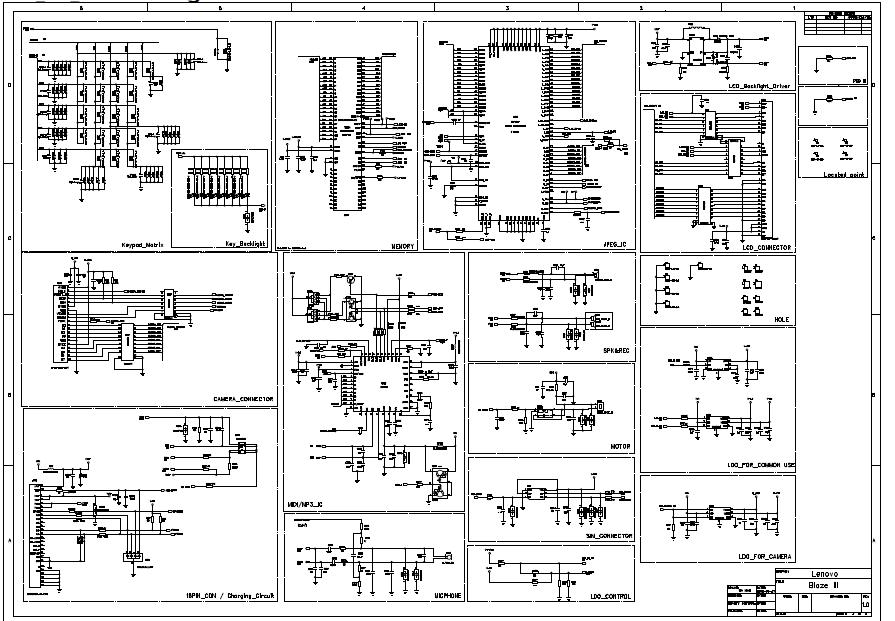
General use camera backlighting baseband circuit: the circuit includes a table of contents, Calyso, iota, matrix, keypad key, memory, IC image, LCD connector, LCD backlight driver, locate points, holes, Speaker4, camera connector, motor, MIDI/MP3 ICs, charging circuit, microphone phone,...
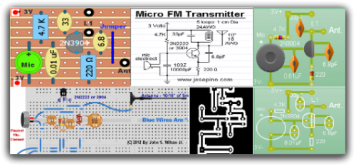
Radio-Circuits has elevated the standard with this website. Unlike any other circuit site on the internet, they have compiled ten of the most popular FM transmitter circuits. Radio-Circuits provides a comprehensive collection of FM transmitter circuits, showcasing a variety of...