
Electronic Doorbell Circuit
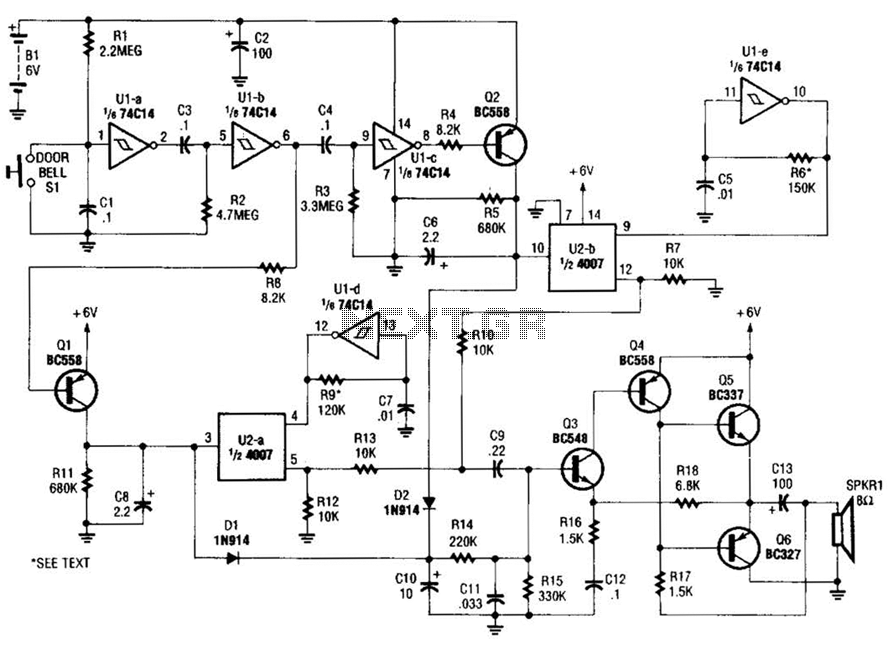
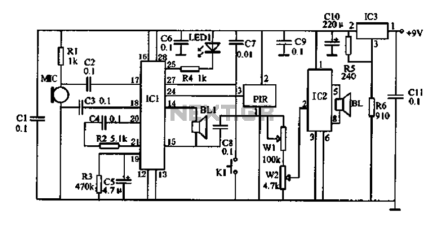
The described circuit functions as a doorbell chime system, employing two monostable multivibrators that operate in a sequential manner. Upon activation of the doorbell switch, the first monostable stage is triggered, producing a short pulse that initiates the operation of the second stage after a predetermined delay. This sequence creates a distinct pattern of activation that is essential for generating a unique audio signal.
The voltage-controlled resistors (VCRs) play a critical role in shaping the audio output. By adjusting the resistance based on the control voltage received from the monostable stages, the VCRs allow for nuanced modulation of the tone generators' outputs. The tone generators are typically configured to produce specific frequencies that correspond to the desired chime sound.
The audio signals produced by the tone generators are then routed to an audio amplifier, which boosts the signal strength to drive a speaker effectively. The amplifier ensures that the sound produced is loud enough to be heard clearly at a distance. The final output is delivered through the speaker, providing an audible indication of someone at the door.
This schematic illustrates a straightforward yet effective approach to designing a doorbell chime system, integrating sequential logic with audio modulation techniques to create a pleasant and functional alerting mechanism. When the doorbell switch is pressed, the two monostable stages are activated in sequence, applying bias to a pair of voltage-controlled resistor stages. These then modulate the outputs from a pair of tone generators. The resulting signals are fed to an audio amplifier, then to the speaker. 🔗 External reference
Related Circuits
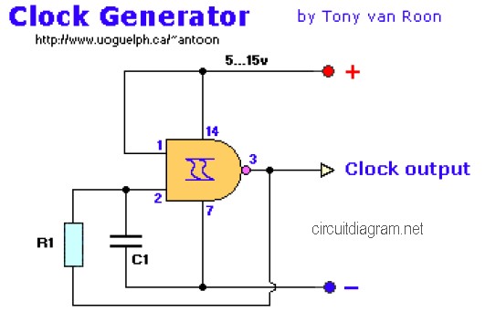
The following diagram is the clock generator circuit diagram built using NAND gate logic integrated circuits (ICs). The circuit can utilize either the IC 7400, which is a TTL type, or the IC 4011, which is a CMOS type....

A compilation of the best free Android applications for electronics and electrical engineers, including simulators, resistor color code tools, and electronic toolkits. The compilation of Android applications for electronics and electrical engineers serves as a valuable resource for professionals and...
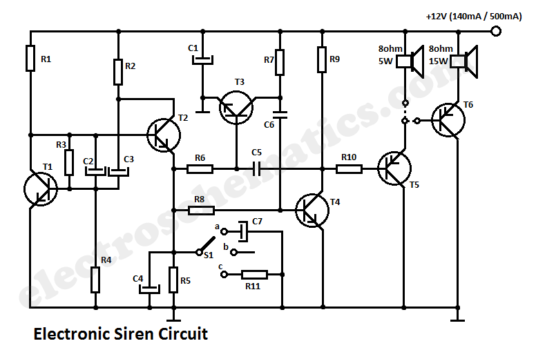
This circuit generates a tone that resembles a siren. The generator section consists of a combination of PNP and NPN transistors that form a free-running multivibrator. If capacitor C2 were connected to the positive line of the power supply,...
Electronic Schematic Circuit Diagrams Manual PDF Download. The document provides a comprehensive manual that focuses on electronic schematic circuit diagrams. These diagrams are essential tools for understanding and designing electronic circuits, offering visual representations of circuit components and their interconnections....
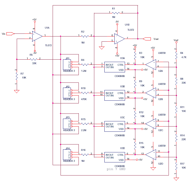
This circuit adjusts the gain of operational amplifier U1B in four distinct steps or segments. It is designed to achieve a linear output from various transducers at levels of 1%. Operational amplifier U1A serves as a buffering amplifier to...
Doppler effect sensor N1 (RD627), operational amplifier N2 (LM358), and a special integrated circuit for imitating dog barking (N3, KD5608) are utilized along with other components. When there is no activity detected in the monitoring area by N1, the...