
Easy 24C I2C Serial EEPROM Interfacing with AVR Microcontrollers
#include <avr/io.h>
#include "util/delay.h"
#include "24c64.h"
#include "lcd.h"
/* A simple delay routine to wait between messages given to the user so that they have time to read them */
void Wait() {
uint8_t i;
for(i = 0; i < 100; i++) _delay_loop_2(0);
}
void main() {
// Variables
uint8_t failed;
unsigned int address;
// Initialize LCD
LCDInit(LS_BLINK);
// Initialize EEPROM
EEOpen();
_delay_loop_2(0);
LCDClear();
LCDWriteString("External EEPROM");
LCDWriteStringXY(0, 1, "Test");
Wait();
LCDClear();
LCDWriteString("Writing. ");
// Fill the entire EEPROM (8KB or 8192 bytes) with the number 7
failed = 0;
for(address = 0; address < 8192; address++) {
if(EEWriteByte(address, 7) == 0) { // Write Failure
failed = 1;
}
}
// Read back the data to verify
for(address = 0; address < 8192; address++) {
uint8_t value = EEReadByte(address);
if(value != 7) {
failed = 1;
break;
}
}
if(failed == 0) {
LCDWriteString("Write Successful");
} else {
LCDWriteString("Write Failed");
}
}
This sample program serves as a practical demonstration of interfacing with an external EEPROM, providing a foundational understanding for hardware and software interactions in embedded systems. The use of the LCD library enhances user interaction by displaying real-time feedback during the EEPROM operations.An EEPROM is kinds of novalatile memory, that means it is used for storing digital data permanently without any power suply. EEPROM stands for Electrically Erasable Programmable Read Only Memory. The advantage of these kind of ROMs is that they can be erased Electrically to make them ready for storing new data.
Compare this with a CD R disks they can be recorded only once. A small amount of EEPROM is also available internally on the AVR chips. So if the volume of data you want to store is small (say few user names and password) then you can use it. The internal eeprom makes design small and simple. But if the amount of data you want to store is large, say in order of few tens of kilobytes then you have to interface a External EEPROM chip with your AVR MCU.
You can store pictures, sound and long texts in these eeproms. Their are many kinds of EEPROM chip available from many manufactures. One very common family is 24C series serial EEPROMs. They are available upto 128KB in size. They uses I2C interface with host controller (MCU) which is a very popular serial communication standard. I will write more indept tutorial on I2C in comming days and in this tutorial I will give you easy to use function that you can use without any knowledge of I2C interface.
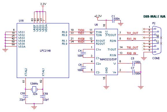
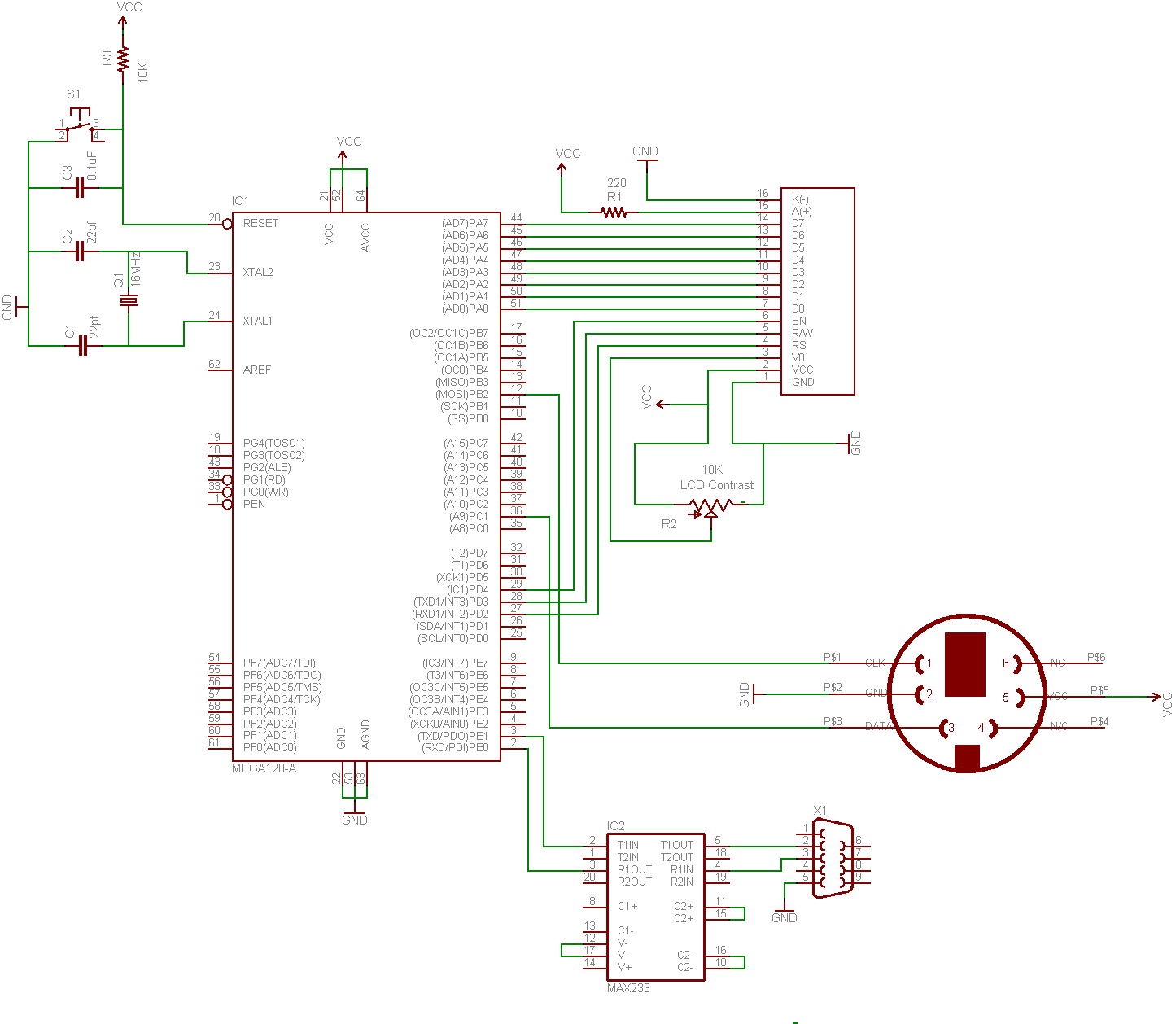
The chip has storage location which have their unique address ranging from 0-8191. Consider these as storage cells so while storing and retriving data you have to tell the chip which cell location you want to read. For exaple if you read location 0003 you will get 99 (see image above). Note each cell can store 8BITs of data so range you can store is 0-255 (-128 to +127). So if you want to store bigget data like int you have to store them in two cells. Connect your ATmega32 with 24C64 chip as shown in the circuit diagram. You can use any avr development board for the purpose or assemble the whole circuit in a Breadboard or Veroboard.
The following sample program demonstrate the use of external EEPROM interfaing functions. The program makes use of the LCD library for AVRs to display information in a 16x2 LCD display. The program first writes 8Kbytes of data to a 24c64 eeprom to fill the whole eeprom with `7` and then it reads back to see if all the location has 7. If the condition is met the screen shows "Write Successfull" message. I have used my xBoard - An Advance ATmega32 development board to test the routines. You can use any devboard with ATmega16 or ATmega32 MCUs. The 24C64 was mounted on a Breadboard. /* A sample program to test the Extrenal EEPROM interfacing routines. The program fills the whole EEPROM with 7 and then reads the whole EEPROM memory to see if all of them contains 7.
This helps in quick testing of you hardware /software before using these routines in your own programs. The target for this program is ATmega8, ATmega16, or ATmega32 running at 16MHz. If you use slower crystal the program will simply run slow but without any problems. This program also makes use of eXtreme Electronics 16x2 LCD Interfacing routines. See the related page for more info Author : Avinash Gupta Date : 16 March 2009 Mail : me@avinashgupta.
com Web : NOTE: IF YOU USE THIS LIBRARY IN YOUR PROGRAMS AND FINDS IT USEFUL PLEASE MENTION US IN CREDIT AND RECOMEND OTHERS. */ #include
"); //Fill whole eeprom 8KB (8192 bytes) //with number 7 failed=0; for(address=0;address<8192;address+) { if(EEWriteByte(address, 7)=0) { //Write Fail 🔗 External reference
Related Circuits
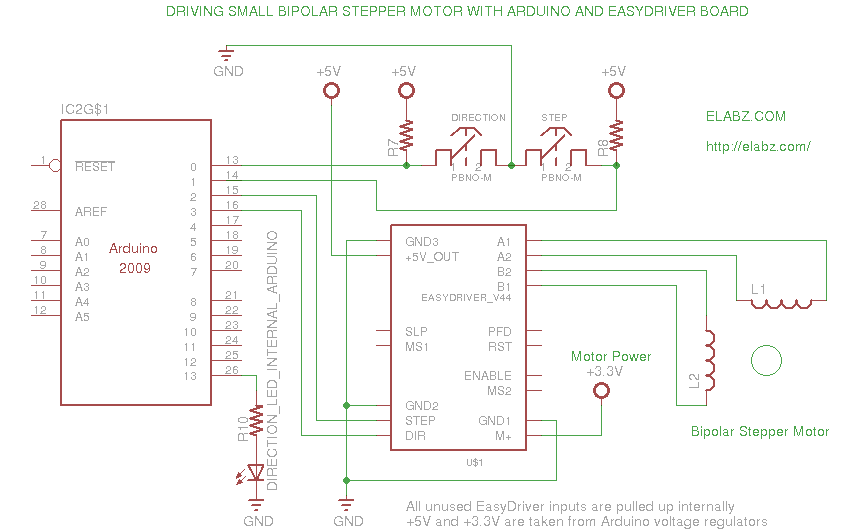
A video and the circuit with schematics for connecting and controlling the world's smallest linear actuator based on a bipolar stepper motor from a Blu-ray drive. The project involves the design and implementation of a circuit to control a linear...
These parameters are expected with an approximately 50% square wave up to frequencies of several MHz, and symmetric sine waves at higher frequencies. The primary limitation is based on the maximum clocking rate specification for the MM74HC6040 ripple counter...
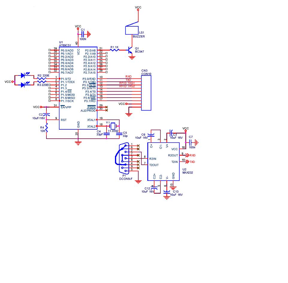
A project is being developed utilizing RFID (Radio Frequency Identification) technology. The microcontroller chosen for this project is the AT89C51/52/S52. Serial communication is being implemented using RS-232. The project involves the integration of RFID technology for identification and data exchange...
The circuit illustrates how to interface a Wi-Fi module with a microcontroller. The Wi-Fi module continuously transmits and receives serial data using the RS232 protocol over the internet without the need for wires. It facilitates data reception and transmission...
This guide demonstrates how to create a simple terminal using a keyboard, LCD screen, and an 8-bit microcontroller. A portable terminal can be useful for troubleshooting a headless server, building a minicomputer from a WRT, or learning how to...
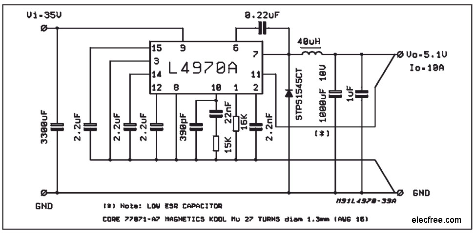
A compact and easy-to-build 5V 10A power supply circuit is sought. This circuit utilizes the L4970A IC as a 10A switching regulator. It is designed to be straightforward, serving as an example of an integrated ready-made circuit. An important...