
Super simple serial terminal
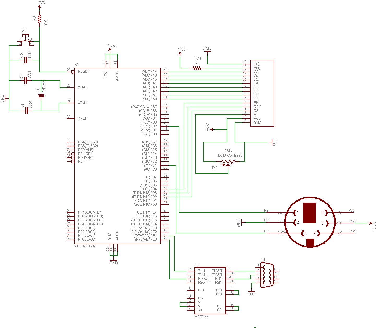
The circuit described involves several essential components working in unison to create a functional dumb terminal. The ATMEGA128 microcontroller serves as the central processing unit, executing the code that manages the keyboard input and LCD output. The microcontroller operates at a frequency of 16 MHz, which provides sufficient processing speed for handling serial communication and display updates.
The MAX233 chip is critical for interfacing the microcontroller with RS-232 standards. It converts the 5V logic levels of the microcontroller to the 12V levels required by RS-232 communication. This ensures that the signals are compatible and prevents damage to the microcontroller. The connection between the MAX233 and the ATMEGA128 should be made with care, ensuring that the RX and TX pins are properly aligned to facilitate bidirectional communication.
The LCD used in this project is a 20x4 character display based on the HD44780 controller, which is widely recognized for its ease of use with microcontrollers. The LCD requires a few control lines (RS, RW, E) and data lines (D0 to D7) for proper operation. In this setup, the microcontroller sends commands and data to the LCD based on user input from the keyboard. The library associated with the HD44780 simplifies the process of sending commands and displaying characters, allowing for quick development and prototyping.
The keyboard communicates through a serial protocol that uses two lines: DATA and CLOCK. The microcontroller must be programmed to listen for changes on these lines. When a key is pressed, the DATA line transitions low, signaling the start of a transmission. The microcontroller must read the data on the falling edge of the CLOCK signal, capturing the scancode in reverse order. This requires careful timing and bit manipulation within the code to ensure accurate interpretation of the scancode.
In summary, this project illustrates the integration of a keyboard, LCD, and microcontroller to form a portable dumb terminal. The use of RS-232 for communication with a headless Linux system, combined with the capabilities of the ATMEGA128 and MAX233, creates a versatile tool for various applications, from server management to educational purposes. The implementation of the HD44780 LCD and the straightforward keyboard communication protocol further enhances the functionality of the terminal, making it an invaluable resource for users.This hack shows how to make a dumb terminal out of a keyboard, LCD screen, and an 8-bit microcontroller. From time to time, a portable dumb terminal can be handy for when you have to rescue a headless server that`s acting up or if you are building a minicomputer out of a WRT, or if you just want to learn how to run a keyboard and LCD screen with a
microcontroller. This super simple serial terminal will use RS-232 to control a headless linux system. Additionally, you might want to check into some of the command line interface programs that allow web browsing, AIM and IRC chatting and more directly from the terminal, but nothing beats being able to track your pizzas with this device. The Linux system in question here will be Linux Mint. It`s a young distro based on Ubuntu that`s gaining a lot of attention lately, though the principles can be used for other Linux distros.
For this How-To we`ll be using an ATMEGA128 running at 16MHz. Since this device will be communicating through RS-232, we`re going to need a level shifter. RS-232 uses 12 volt signals which will fry our 5V microcontroller. To fix this problem, we`re going to use a MAX233 chip. I`m using the ET-AVR stamp module with the stamp board for this project. This dev board is cheap and has the essentials built in. I`ll be using the on board power supply and the MAX232 RS-232 level converter. The LCD chosen for this project is a very common 4G—20 character LCD. These LCDs are really easy to control with a microcontroller (PDF), and even without one (PDF). The HD44780 chip allows for several bit widths for parallel programming, as well as commands, and even custom characters. This LCD has nice software library, which makes it even easier to use. A more attractive choice would have been to go with a graphical LCD, which are also supported by our library, however, we only had the character LCD on hand.
We used WinAVR with AVRlib installed. AVRlib is a set of libraries that can run servos, set up A/D conversions, etc. It can do pretty much anything else you need it to do. To install WinAVR, get the newest version here and follow the directions on the installer. We generally don`t follow the directions here for installing AVRlib and place it into the include folder of WinAVR installation found at C:/WinAVR/avr/include/AVRlib. This way your included headers are easier to see and find. Once this is done, you can open up Programmer`s Notepad and begin coding. We`ve already written the code for this project (with room left over for some adventurous readers to modify).
Keyboards use a simple serial communication setup. There are only 2 lines, the DATA and the CLOCK. Generally, nothing is happening on these lines (both the CLOCK and DATA lines are high) until you hit a key. Once a key is pressed, the DATA line goes low. Shortly thereafter, the CLOCK falls. The clock will go for a total of 11 cycles. As this happens, data must be read form the DATA line on the falling edge of the clock. The data is sent from the keyboard in reverse (least significant bit first) with a parity and a stop bit.
Looking at an example, it is easier to understand. Imagine the m` key has been hit on the keyboard. The data line goes low to make a start bit, then the scancode is sent with the LSB first, then the parity (odd parity) and a stop bit. Since the scancode for m` is 0x3A, we should get that value in the data portion of the package. Again, the keyboard sends data LSB first, so since we are expecting 0x3A (binary 00111010) we will actually get the reverse of that (binary 010111100).
Just remember to read the data bits from right to left to make it easier to see the scancode. After the data, we`ll receive a 1 in the parity bit to make the package odd parity, then the stop bit. After the scan code has been sent, the keyboard will send another scancode when the button has been released.
This release code is always 0xF0 and can be ignored, and i 🔗 External reference
Related Circuits
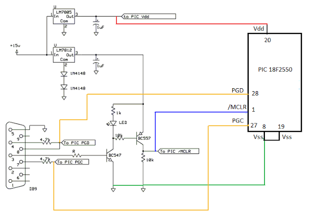
This is a simple COM port-based Microchip PIC microcontroller programmer, which is based on the JDM programmer. The entire programmer is constructed using commonly available components, allowing the programming of various microcontrollers using this schematic. To program a specific...
This design was created to address a challenge with the tailwheel doors of the P-51 Mustang. The issue arises from the complex undercarriage sequence, which would necessitate two independent sequencers. The closing sequence involves the main gear doors opening,...
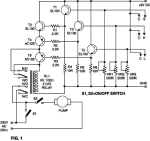
This simple water detector circuit utilizes alternating voltage to prevent the corrosion of the electrodes. It is straightforward to construct and employs N1 as a trigger Schmitt gate that generates the AC signal. When an electrical conductor, such as...
By utilizing logic chips, the behavior of a robot can be enhanced, allowing for the implementation of more complex algorithms. Logic chips, also known as logic gates or digital logic integrated circuits, are fundamental components in digital electronics that perform...
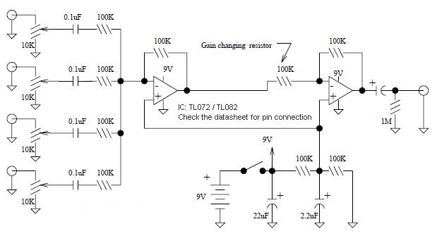
A basic mixer suitable for mixing microphones or effects outputs. The overall gain from input to output is unity if the potentiometer related to the input is fully turned up. This gain can be increased to ten (or any...

As environmental awareness increases, electric cars have become an essential part of people's transportation. Preventing electric car theft is a significant concern for owners. Various electric vehicle anti-theft locks have been developed; however, theft of electric cars continues to...
Warning: include(partials/cookie-banner.php): Failed to open stream: Permission denied in /var/www/html/nextgr/view-circuit.php on line 713
Warning: include(): Failed opening 'partials/cookie-banner.php' for inclusion (include_path='.:/usr/share/php') in /var/www/html/nextgr/view-circuit.php on line 713