
Easy Build FM Transmitter
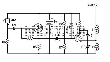
The FM transmitter circuit is designed for simplicity and affordability, making it accessible for hobbyists and those new to electronics. The primary components typically include a transistor for amplification, a few resistors, capacitors for filtering, and an inductor to form the necessary tank circuit for frequency modulation.
When powered at 9V, the transmitter operates efficiently, providing a range of approximately 300 feet, which is suitable for personal use or small events. Increasing the power supply to 12V enhances the circuit's performance, allowing for a maximum transmission range of about 400 feet. This increase in voltage improves the output power of the transmitter, which in turn enhances the signal strength and clarity.
To construct this transmitter, an oscillator circuit is usually implemented, which generates the RF signal. The modulation of the signal can be achieved by varying the input audio signal, typically from a microphone or an audio source. The modulated signal is then amplified by the transistor before being transmitted through an antenna, which can be a simple wire of appropriate length for the desired frequency.
The design may also incorporate additional features such as a low-pass filter to reduce harmonic distortion and improve signal quality, as well as tuning elements to allow for frequency adjustments. Overall, this low-powered FM transmitter serves as an excellent project for learning about radio frequency transmission and basic electronic circuit design.This is a low cost and easy build low powered FM transmitter. The range of the FM transmitter claimed about 300 feets when running at 9V supply. And the range claimed to be increased become about 400 feet when running it at 12V supply. Take.. 🔗 External reference
Related Circuits
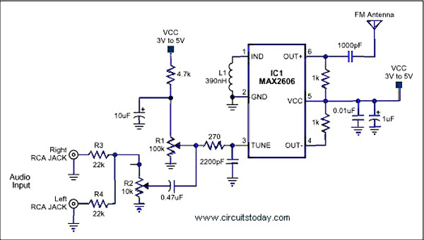
A simple single-chip FM transmitter circuit with a diagram and schematic using the IC MAX 2606, which is a high-performance voltage-controlled oscillator (VCO). The FM transmitter circuit utilizing the MAX 2606 is designed for efficient frequency modulation of audio signals....
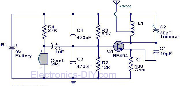
The circuit diagram of a simple FM transmitter utilizing a transistor is presented. While this design may not guarantee exceptional performance or range, it serves as a fundamental example. The circuit employs a general-purpose radio frequency transistor, the BF...

A composite stereo signal, as transmitted by FM radio stations, is composed of at least three parts: A base band mono signal, a double sideband channel difference signal, and a pilot carrier. The signal composition is somewhat analogous to...
L2 RFC (resistance 1MOhm with an inductor wrapped around it made from fine isolated wire. Scratch the inductor and connect it to the resistance, creating a parallel L-R circuit.) With C7 and C8, we adjust the resistance of the...
This guide provides instructions for becoming a radio pirate by creating a low-power FM transmitter to broadcast content on the airwaves. It serves as a follow-up to a recent call for easing restrictions on radio broadcasting in the Maldives....
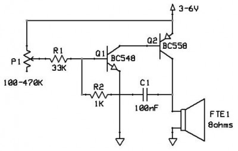
This circuit functions as an oscillator, capable of generating a sound wave or tone. The frequency of the tone, whether high or low, is adjustable via a variable resistor. The volume produced by this circuit is substantial; therefore, it...
Warning: include(partials/cookie-banner.php): Failed to open stream: Permission denied in /var/www/html/nextgr/view-circuit.php on line 713
Warning: include(): Failed opening 'partials/cookie-banner.php' for inclusion (include_path='.:/usr/share/php') in /var/www/html/nextgr/view-circuit.php on line 713