
FM Transmitter 4Watt
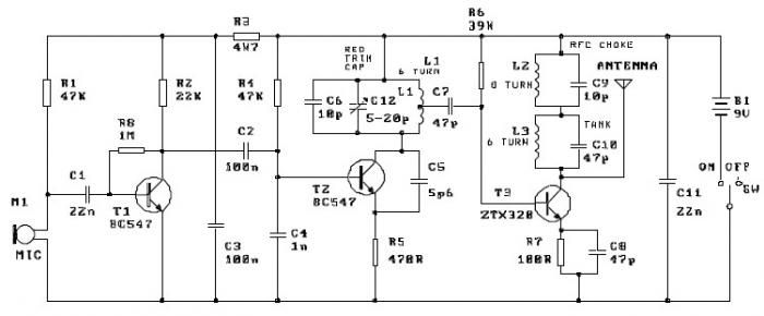
The described circuit involves an L-R (inductor-resistor) configuration where L2 serves as a Radio Frequency Choke (RFC). The RFC is characterized by a resistance of 1 MΩ, which is crucial for filtering out unwanted frequencies while allowing the desired signals to pass through. The inductor is constructed using fine isolated wire, which is coiled to enhance its inductive properties. This coiling increases the inductance, making the RFC effective in suppressing high-frequency noise.
The process of "scratching" the inductor likely refers to a method of creating a physical connection or modifying the inductor to optimize its performance in the circuit. By connecting this inductor in parallel with the resistor, a parallel L-R circuit is formed, which can provide specific impedance characteristics beneficial for radio frequency applications.
Capacitors C7 and C8 are integrated into the circuit to fine-tune the overall impedance, allowing for better adaptation to the aerial system. These capacitors play a vital role in tuning the circuit, ensuring that the resonance frequency aligns with the desired frequency of operation. This tuning is essential for effective signal transmission and reception, particularly when aiming to ensure clear voice communication over the radio.
The overall design emphasizes the importance of component selection and configuration in achieving optimal performance in radio frequency applications. Properly adjusting the values of the resistance and capacitance allows for enhanced audio clarity and reception quality, making the circuit suitable for practical use in radio systems.L2 RFC (resistance 1MOhm with wrapped around her inductor of enough coils from fine isolated wire. Scratch of utmost inductor and you stick in utmost the resistance making thus a parallel L-r circuit. ) With their C7, C8 we adapt the resistance of aerial (practically to them we regulate so that it is heard our voice in the radio as long as you beco
me cleaner). 🔗 External reference
Related Circuits
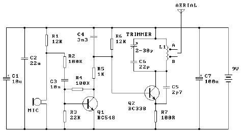
The tuned coil L1 has two output tap points for the antenna connection, labeled "A" and "B." Both outputs are low-level, allowing the user to select between a stable low range or a more unstable but higher range. Tap...
FM Beacon Broadcast Transmitter (88-108 MHz). This circuit will transmit a continuous audio tone on the FM broadcast band (88-108 MHz), which could be used for remote control or security purposes. The FM Beacon Broadcast Transmitter operates within the frequency...
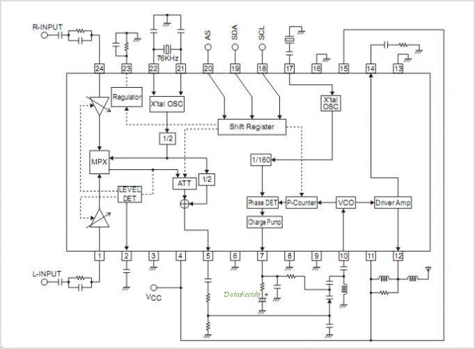
The LV2283VB is an FM Transmitter Integrated Circuit (IC). The multiplex (MPX) block generates a stereo modulated composite signal from left and right audio inputs. The RF Voltage-Controlled Oscillator (VCO) incorporates the FM modulation function. The Phase-Locked Loop (PLL)...
Here is a simple schematic of a TV transmitter circuit, or video transmitter circuit, capable of broadcasting in the VHF range from 60 to 200 MHz. The input video source can be any CCD camera or VCR. The output...
This FM transmitter project is a simple yet effective circuit capable of transmitting signals over a distance of up to 1 kilometer in open air conditions. The circuit employs an RF transistor in the output stage, along with two...
This schematic represents an FM transmitter capable of delivering an output power of 3 to 3.5 W, operating within the frequency range of 90 to 110 MHz. While the stability of the circuit is acceptable, a Phase-Locked Loop (PLL)...