
easy build motocycle alarm

The circuit design incorporates a dual-transistor configuration to control a relay, which in turn activates a buzzer when certain conditions are met. The relay serves as a switch that can be controlled by multiple normally-open switches, allowing for flexibility in the design. Mercury switches are specifically recommended for this application to ensure reliable closure when steering is engaged, providing an effective means of triggering the alarm in response to vehicle movement.
The NE555 timer-based fire alarm circuit operates by utilizing a thermistor, a type of resistor whose resistance varies significantly with temperature changes. At elevated temperatures, the thermistor's resistance decreases, allowing current to flow and activating the transistor. This configuration ensures that the circuit is sensitive to temperature fluctuations, making it suitable for fire detection applications.
In addition, the car alarm simulator functions by monitoring voltage levels in the vehicle. When the car is operational, the alternator generates a voltage that can be detected by the circuit. The LED indicator provides a visual cue to the user, confirming whether the vehicle is running or not.
The car headlight alarm circuit is designed to prevent battery drain by alerting the user when the headlights are left on after the ignition is turned off. This feature is particularly useful for ensuring that the vehicle's battery remains charged and operational.
Finally, the power supply failure alarm circuit presents a unique solution by utilizing an electrolytic capacitor to store charge, eliminating the need for an independent power source. This design is advantageous in situations where power supply reliability is critical, as it can operate autonomously, providing alerts without additional power requirements.The circuit just required 2 transistors to drive the relay the the relay act as a switch to activate the buzzer. Any number of normally-open switches may possibly be applied. Fit the mercury switches to ensure that they close when the steering is. The following circuit is a simple fire alarm circuit based NE555 timer and use thermistor as a temperature detector. This sensor will activate the transistor when the temperature is in high value. The thermistor will have a low resistance at high temperature, while at low temperature, the transistor resistance is high. This characteristic of thermitor. This is a car alarm simulator which using the LED as a simulation output. This simple circuit can tell you whether your car is running or not by detecting the voltage difference when the car is on and off.
This occurs because when your car is running the Alternator puts a out a voltage a. This car headlight alarm circuit can be set for one or two functions: First, to indicate that the head lights (or the side lights) should be switched off after switching off the ignition contact. With this circuit, there should be no dead battery due to headlights that were left on. Second, to indicate that the. This is the `special` circuit design of power supply failure alarm. The vast majority of the power supply failure alarm / indicator circuits require a independent power supply for themselves.
However the alarm circuit introduced right here requires no extra supply power source. It utilizes an electrolytic capacitor to hold sufficient charge, to supply power. 🔗 External reference
Related Circuits
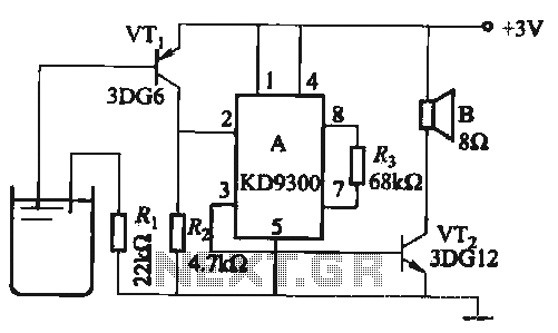
Changing the values of Ri, R2, Cl, and C3 can modify the alarm tone. The circuit utilizes KD9300 music integrated circuits. The circuit described is designed to generate an alarm tone through the manipulation of specific component values within the...

This circuit project automatically activates a night lamp when the bedroom light is turned off. The lamp stays illuminated until the light sensor detects daylight. The circuit operates using a light-dependent resistor (LDR) as the primary sensor to detect ambient...

A filtered 15 V DC supply is applied to a series circuit that includes a thermistor (R2) and a parallel combination of resistors (R1 and R3). The transistor (Q1) functions as a switch, with its state controlled by the...
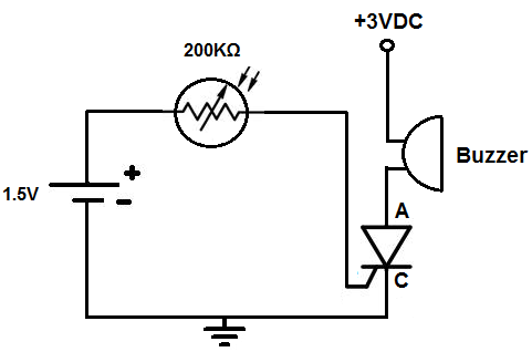
This circuit activates an alarm when it detects a specific level of light. When the light exposure increases beyond a predetermined threshold, a loud buzzer sounds, providing an alert. The alarm remains inactive in low-light conditions but triggers in...

The locker alarm circuit, also known as the cashbox watcher, is designed to safeguard a cashbox or locker from unauthorized access. This reliable design features a foolproof, remotely operated alarm and electromagnetic relay driver that receives its control signal...

The temperature alarm circuit shown in the figure consists of an inverting amplifier (IC1), a comparison amplifier (IC2), a low-frequency multivibrator (IC3), a controllable oscillation frequency multivibrator (IC4), a bridge measurement network, a speaker (Y), and a power supply...